In the dynamic landscape of industrial automation and electrical engineering, proximity sensors are indispensable components. Selecting the correct model is critical for system reliability, safety, and performance. However, deciphering the alphanumeric codes that constitute a sensor's model number can be a daunting task. This guide provides a systematic approach for engineers and technicians to accurately identify and interpret proximity sensor models, ensuring proper selection, replacement, and integration.
The model number of a proximity sensor is its unique identifier, encoding vital specifications within a compact string of characters. While manufacturers have their own naming conventions, most follow a logical structure that reveals key parameters. The first step is to locate the model number, typically found on the sensor's housing label or in the technical datasheet. Never rely on visual appearance alone for identification.
A standard model number is usually segmented. The initial segment often denotes the sensor series or family. For instance, prefixes like "E2E" or "XS" might indicate a specific product line from a particular manufacturer, encompassing a range of sensors with similar design principles. Recognizing the manufacturer from this prefix is the first key. Brands like Omron, Siemens, Pepperl+Fuchs, and Schneider Electric have distinct series identifiers.
Following the series code, the model number typically specifies the sensing type. This is arguably the most critical distinction. Common abbreviations include:
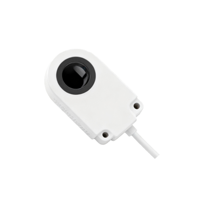
IN: Inductive proximity sensor (for detecting metallic objects).
CA: Capacitive proximity sensor (for detecting both metallic and non-metallic materials).
UR: Ultrasonic sensor.
OP: Optical or photoelectric sensor.
Sometimes, a single letter like "L" for inductive or "C" for capacitive is used. Identifying this code confirms the fundamental working principle.
The next set of characters usually defines the physical form factor and mounting style. Codes might indicate:
CYL: Cylindrical barrel shape.
BLK: Rectangular or block shape.
FLUSH: Flush-mountable.
NON-FLUSH or EMB: Non-flush or embeddable.
THREAD size (e.g., M8, M12, M18, M30) is often integrated here or immediately after.
Subsequent digits or letters frequently denote the sensing distance, a paramount specification. For example, "5" might indicate a 5mm range, "10" for 10mm, and so on. Some manufacturers use a code that corresponds to a range listed in their catalog. Always cross-reference this with the datasheet for the exact nominal sensing distance (Sn).
The output configuration is another essential element encoded in the model string. This defines the electrical interface:
NPN-NO: NPN transistor, normally open.
NPN-NC: NPN transistor, normally closed.
PNP-NO: PNP transistor, normally open.
PNP-NC: PNP transistor, normally closed.
2W: 2-wire AC/DC.
3W: 3-wire DC.
4W: 4-wire (dual output).
Codes like "E2" might represent a PNP output, while "A" could signify a DC 3-wire type. Incorrect interpretation here can lead to circuit damage.
Further suffixes often specify:
Connection Type: "C" for connector, "L" for cable lead, "P" for pre-wired, "M8" or "M12" for quick-disconnect.
Housing Material: "S" for stainless steel, "B" for brass, "P" for plastic.
Special Features: "T" for temperature resistance, "V" for washdown/chemical resistance, "E" for extended range, "I" for IO-Link capability.
Practical Example: Consider a model "E2E-X10ME1-Z" from a common manufacturer.
E2E: Inductive proximity sensor series.
X: Extra-small form factor.
10: 10mm sensing distance.
M: M12 threaded barrel.
E: PNP NO output.
1: Shielded (flush mountable).
Z: DC 3-wire, cable connection.
When in doubt, the authoritative resource is always the manufacturer's official datasheet or product catalog. Use the full model number to search for the precise technical document online. Many manufacturers provide online selection tools or detailed breakdowns of their part numbering systems.
Mastering the art of reading model numbers streamlines procurement, troubleshooting, and maintenance. It empowers engineers to make informed decisions, ensuring compatibility with power supplies