In the realm of industrial automation, particularly within CNC (Computer Numerical Control) cutting and routing machinery, the reliability and precision of the entire system hinge on a network of seemingly minor components. Among these, proximity switch sensors stand as critical sentinels, ensuring operational safety, positional accuracy, and process repeatability. This article delves into the function, selection, application, and troubleshooting of proximity switch sensors specifically within the context of CNC cutting machines, commonly referred to as panel saws or开料机.
A proximity switch sensor is a non-contact electronic device designed to detect the presence or absence of a metallic target object within its sensing range without any physical contact. In CNC cutting machines, these sensors are ubiquitously deployed for limit sensing, homing sequences, tool presence verification, and safety interlocking. Their non-contact nature eliminates mechanical wear, provides high switching frequency, and ensures long-term reliability in dusty, chip-laden environments typical of woodworking, composite, and metal sheet processing.
The operational principle is primarily based on electromagnetic induction for inductive types, which are the most common in this application. The sensor generates an oscillating electromagnetic field. When a metallic object (e.g., the machine gantry, saw carriage, or a tool holder) enters this field, eddy currents are induced in the target, causing a change in the oscillation amplitude. This change is detected by the sensor's circuitry, which subsequently triggers a solid-state switch to change state (PNP or NMP output). This signal is then fed directly into the machine's Programmable Logic Controller (PLC) or motion controller.
Key specifications for engineers selecting a proximity sensor for a cutting machine include:
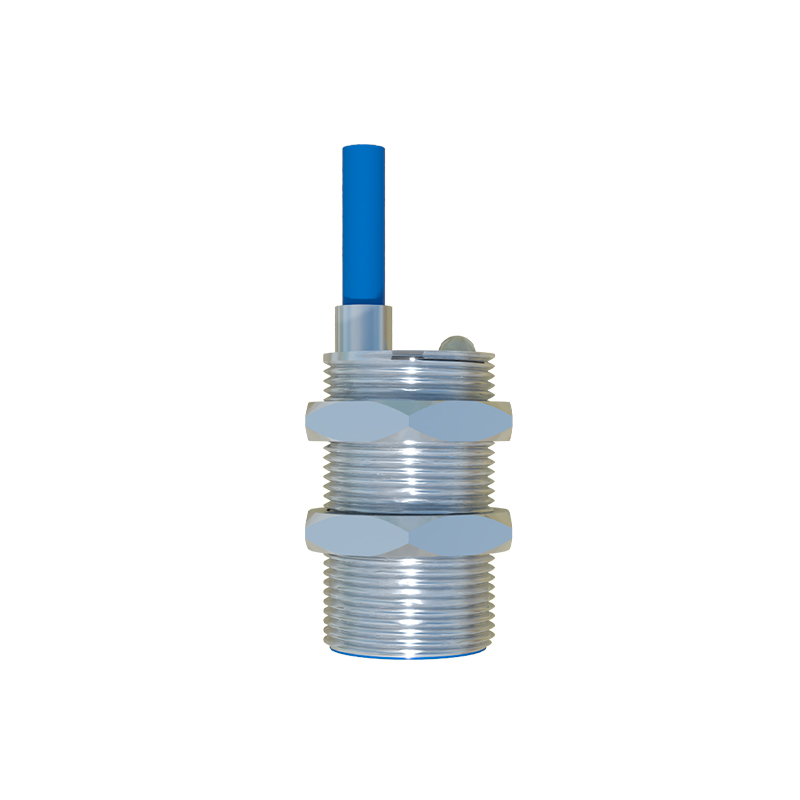
1. Sensing Distance: The nominal range (e.g., 5mm, 8mm) must be chosen with a safety margin, considering machine vibration and thermal expansion.
2. Target Material: Inductive sensors detect ferrous (steel, iron) and non-ferrous metals (aluminum, copper) with different effective ranges. The target material on the machine must be specified.
3. Output Configuration: PNP (sourcing) or NPN (sinking) outputs must match the input card of the PLC. DC 3-wire configurations are standard.
4. Housing Material: Stainless steel or nickel-plated brass housings offer resistance to coolant, dust, and physical impact.
5. Switching Frequency: High-speed applications, like spindle speed monitoring, require sensors with kHz-range frequencies.
6. Protection Rating: A minimum of IP67 is recommended to withstand washdown and particulate ingress.
In a typical CNC cutting machine, proximity sensors are strategically positioned. Key applications are:
- Axis Limit Switches: Sensors at the extreme ends of the X, Y, and Z axes prevent over-travel and potential mechanical damage. They define the machine's physical working envelope.
- Homing/Reference Sensors: A dedicated sensor on each axis provides a precise reference point. Upon machine startup, all axes move until they trigger this "home" sensor, establishing a known coordinate zero point for all subsequent movements.
- Tool Detection: Sensors can verify the presence of a saw blade or router bit in the holder, preventing a "tool-less" operation cycle.
- Safety Door Monitoring: Sensors ensure access doors or guards are closed before initiating a cutting cycle, complying with safety standards like ISO 13849.
- Material Presence Sensing: Sensors can confirm a panel is correctly loaded on the bed before processing begins.
Installation and alignment are paramount. The sensor must be securely mounted to resist vibration. The sensing face must be parallel to the target's approach path, maintaining a consistent air gap slightly less than the nominal sensing range. Shielding (e.g., metallic machine frames) can sometimes cause false triggering if not properly accounted for; maintaining distance from large metal masses is crucial.
Troubleshooting common sensor issues involves a systematic approach:
1. No Signal: Verify power supply (typically 10-30V DC). Check wiring for breaks or loose connections. Confirm the target is within range and is of the correct material. Use a voltmeter to test for output voltage change when the target is presented.
2. Intermittent Operation: Often caused by loose mounting, excessive vibration altering the air gap, or buildup of dust/chips on the sensor face. Clean the sensor regularly.
3. False Triggering: Can be induced by electromagnetic interference from motor drives or welding equipment nearby. Ensure proper cable routing (away from power lines), use shielded cables, and check grounding. Adjacent sensors might interfere if mounted too closely.
4. Shortened Sensing Range: This may indicate a failing sensor or a dirty/coated sensing face. It can also occur if the target material is changed (e.g., from steel to aluminum).
The evolution towards Industry 4.0 and IoT