In industrial automation and control systems, proximity sensors play a critical role in detecting the presence or absence of objects without physical contact. Among various configurations, the 24V two-wire proximity sensor stands out for its simplicity, reliability, and ease of integration into DC-based circuits. This article delves into the schematic principles of a typical 24V two-wire proximity sensor, explaining its operation, key components, and wiring considerations.
A 24V two-wire proximity sensor is essentially a solid-state switching device designed to operate on a 24V DC power supply. Unlike three-wire sensors that have separate power, ground, and signal wires, the two-wire version combines the power and switching functions into a single pair of wires. This design reduces wiring complexity and cost, making it a popular choice for applications where space and budget are constrained. The schematic of such a sensor can be broken down into several core components: the oscillator, demodulator, output stage, and protection circuitry.
At the heart of the sensor is an LC oscillator circuit, which generates a high-frequency electromagnetic field. When a metallic object (ferrous or non-ferrous, depending on the sensor type) enters this field, eddy currents are induced in the object, causing a change in the oscillator's amplitude or frequency. This change is detected by the demodulator circuit, which converts it into a DC signal. The output stage then uses this signal to control a solid-state switch, typically a MOSFET or bipolar transistor, that modulates the current flow through the two wires.
In the schematic, the two wires are connected in series with the load (e.g., a PLC input, relay, or indicator). One wire is linked to the positive 24V DC supply, while the other connects to the load, which then returns to the negative side of the supply. When no target is detected, the sensor draws a small leakage current (usually a few milliamps) to power its internal electronics, but the switch remains off, preventing significant current flow to the load. Upon detection, the switch turns on, allowing current to pass through the sensor and energize the load. This behavior mimics a normally open (NO) switch, though normally closed (NC) versions are also available.
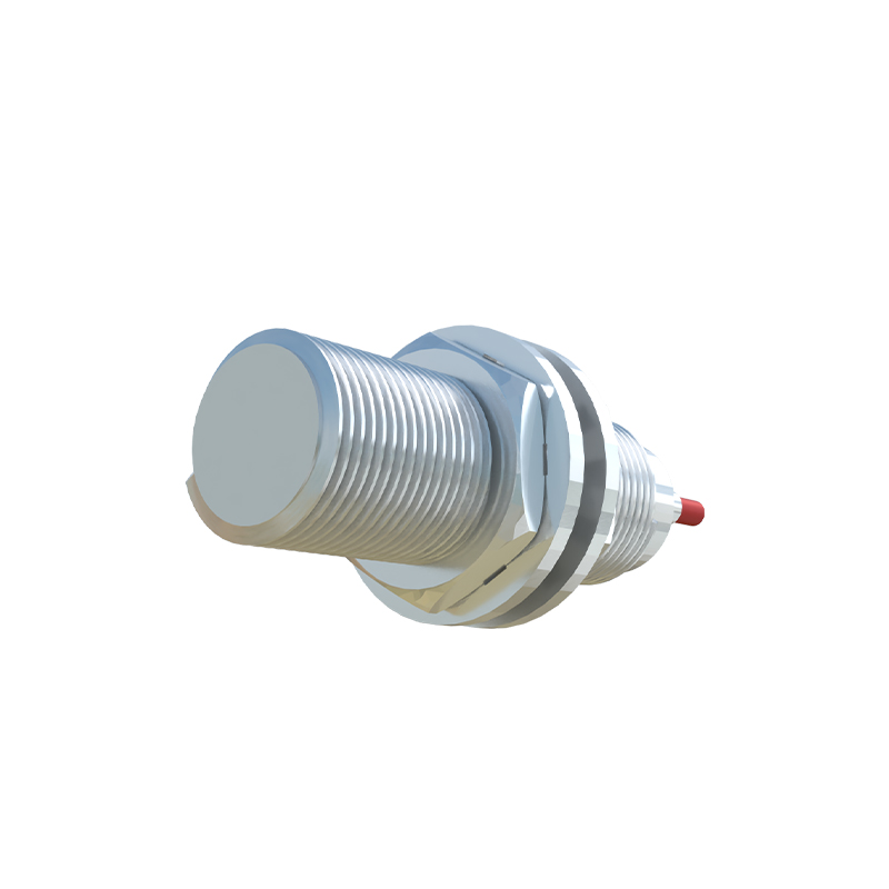
Key aspects of the schematic include protection features such as reverse polarity protection, often implemented with a diode in series or a bridge rectifier, ensuring the sensor is not damaged if wired incorrectly. Additionally, transient voltage suppression diodes or varistors may be included to guard against voltage spikes from inductive loads or electrical noise in industrial environments. The current-limiting resistor in series with the output switch is crucial for defining the sensor's operating current range, typically between 1-10 mA for leakage and 5-100 mA for switching, depending on the model.
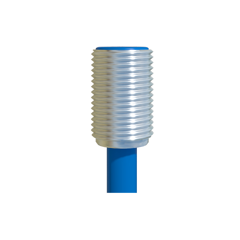
Wiring a 24V two-wire proximity sensor requires attention to voltage drop and load compatibility. Since the sensor and load share the same current path, the voltage drop across the sensor (usually 2-4V) must be accounted for to ensure the load receives adequate voltage. For instance, with a 24V supply, the load might see around 20-22V during operation. It's essential to verify that the load's minimum operating voltage is met. Moreover, the sensor must be matched with a load that falls within its specified current ratings; too low a load may not draw enough current to keep the sensor active, while too high a load could overheat the output stage.
In practice, these sensors are widely used in machinery, conveyor systems, and automotive assembly lines for tasks like position sensing, counting, or limit switching. Their two-wire design simplifies installation, especially in retrofit scenarios, and reduces potential failure points. However, users should note that the leakage current, though small, can sometimes cause false triggers with highly sensitive loads, so testing under actual conditions is recommended.
To summarize, the 24V two-wire proximity sensor schematic embodies a clever integration of sensing and switching functions. By understanding its internal circuitry—oscillator, demodulator, output switch, and protections—engineers can effectively deploy these sensors in diverse industrial settings. Always refer to the manufacturer's datasheet for specific details on wiring, voltage ranges, and environmental ratings to ensure optimal performance and longevity.
