In industrial automation and control systems, proximity switches are indispensable components for detecting the presence or absence of objects without physical contact. Genuine sensors, particularly those from reputable manufacturers, ensure reliability, accuracy, and longevity in harsh environments. This article provides a comprehensive guide to wiring diagrams for genuine proximity switches, covering key principles, configurations, and best practices to optimize performance and safety.
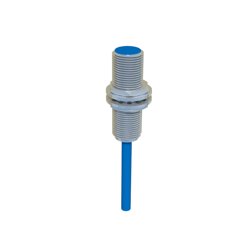
Proximity switches operate based on electromagnetic, capacitive, or inductive principles, with inductive types being most common in metal detection applications. A genuine sensor typically includes a sensing head, housing, and cable or connector terminals. The wiring diagram is crucial for proper installation, as incorrect connections can lead to malfunction, damage, or safety hazards. Most proximity switches have three or four wires, color-coded according to international standards (e.g., IEC or NAMUR). For a standard 3-wire DC sensor, the wires are usually brown (positive), blue (negative), and black (output). In 4-wire versions, an additional white wire may provide a second output or diagnostic function.
The wiring process begins with power supply connections. Ensure the voltage matches the sensor’s specifications—commonly 10-30V DC for DC sensors or 90-250V AC for AC types. Connect the brown wire to the positive terminal and the blue wire to the negative or ground terminal. For AC sensors, typically two wires (often brown and blue) connect to live and neutral lines, with a black output wire. Always refer to the manufacturer’s datasheet, as colors can vary by brand or model. The output wire (black) links to the load, such as a programmable logic controller (PLC) input, relay, or indicator. In sinking (NPN) configurations, the output connects to the negative side, while sourcing (PNP) setups connect to the positive side. Choose based on the control system’s requirements to avoid compatibility issues.
Shielding and grounding are critical for noise immunity, especially in environments with motors or frequency drives. Use shielded cables, connecting the shield to ground at one end only (usually the control panel side) to prevent ground loops. Maintain proper cable routing, keeping sensor wires away from high-voltage lines to reduce electromagnetic interference. For hazardous areas, intrinsic safety barriers may be required, following guidelines like ATEX or IECEx.
Testing and verification involve applying power and checking the output state with a multimeter or PLC monitor. An object within the sensing range should trigger the output, indicated by a voltage change or LED activation on the sensor. Adjust the sensing distance if needed, but note that genuine sensors offer stable performance with minimal drift over time. Regular maintenance includes inspecting connections for corrosion, ensuring tight terminals, and cleaning the sensing face to avoid false triggers.
In summary, wiring genuine proximity switches correctly enhances system efficiency and reduces downtime. By adhering to standardized diagrams, manufacturer instructions, and safety protocols, engineers can achieve robust automation solutions. Always prioritize quality components—genuine sensors may have higher upfront costs but deliver superior durability and precision in the long run.