Inductive proximity sensors are fundamental components in modern industrial automation, playing a critical role in object detection, positioning, and process control without physical contact. Their manufacturing is a precise and multi-stage process that demands a deep understanding of electromagnetic principles, material science, and robust engineering practices. This article delves into the core production stages of these ubiquitous sensors, providing insights valuable for electrical engineers involved in design, application, or system integration.
The heart of an inductive proximity sensor is its coil and ferrite core assembly. Manufacturing begins with the meticulous design and winding of this coil. High-grade copper wire, typically with polyurethane or similar insulation, is wound onto a precision-machined bobbin. The number of turns, wire gauge, and winding pattern are calculated to achieve the desired inductance and quality factor (Q-factor), which directly influence the sensor's sensitivity, switching frequency, and temperature stability. Automated winding machines ensure consistency and repeatability, which are paramount for mass production. The wound coil is then often impregnated with a varnish or resin to secure the windings, enhance mechanical stability, and provide protection against humidity and vibration.
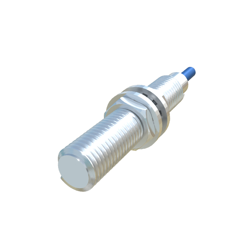
Following coil preparation, the assembly is integrated with a ferrite core. Ferrite materials, chosen for their high magnetic permeability and low eddy current losses at high frequencies, are sintered into specific shapes—often cup-cores or E-cores—to concentrate the oscillating magnetic field. The coil is precisely positioned within or around this core structure. This sub-assembly is then potted or encapsulated within the sensor housing using a thermosetting epoxy resin. This potting compound serves multiple vital functions: it physically secures the delicate internal components, provides exceptional protection against harsh environmental factors like moisture, dust, chemicals, and mechanical shock, and also plays a role in the thermal management of the device.
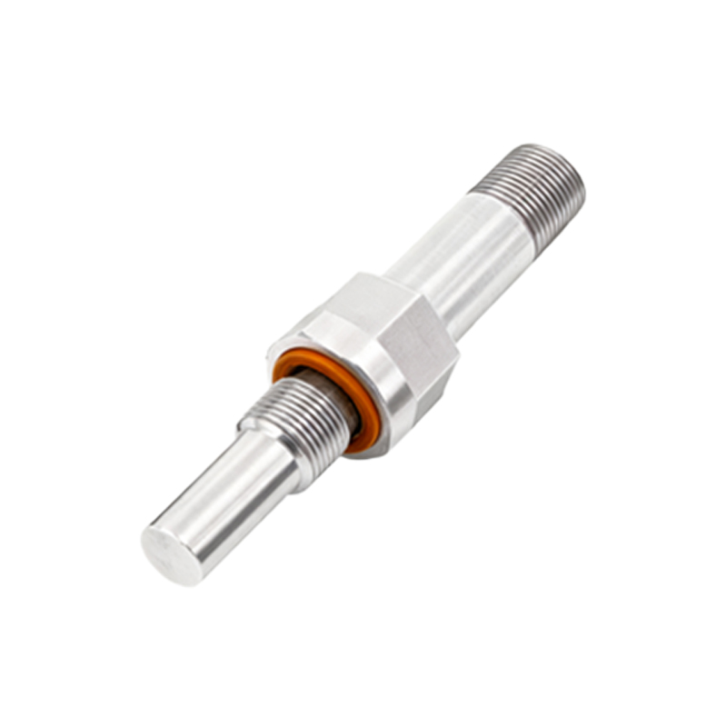
The next critical phase involves the integration of the electronic oscillator and evaluation circuit. The coil and core form part of an LC oscillator circuit that generates a high-frequency electromagnetic field at the sensor's active face. When a metallic target enters this field, eddy currents are induced in the target, which dampens the oscillation amplitude. Sophisticated evaluation circuitry, now predominantly based on application-specific integrated circuits (ASICs), monitors this change. The circuit design must account for factors like temperature compensation to minimize drift, immunity to electromagnetic interference (EMI), and the provision of various output types (e.g., NPN/PNP, NO/NC, analog, or IO-Link). Surface-mount technology (SMT) is universally employed to populate the printed circuit board (PCB) with these components, ensuring high density, reliability, and automated assembly.
The housing and active face material selection is equally crucial. Sensor bodies are typically manufactured from corrosion-resistant materials such as stainless steel (e.g., 303, 304, or 316 grades), brass with nickel plating, or engineered plastics like PBT or PPS for non-metallic applications. The active face, from which the magnetic field emanates, is often a specific grade of stainless steel or a specialized plastic composite that allows the field to pass through while protecting the internal components. The machining and finishing of these housings require high precision to ensure proper sealing (often achieving IP67, IP68, or IP69K ratings), correct thread dimensions, and consistent sensing characteristics.
Finally, the assembled sensor undergoes rigorous calibration and testing. This is not a mere pass/fail check but a comprehensive validation process. Key parameters tested include the rated operating distance (Sn), hysteresis, repeat accuracy, response frequency, temperature range performance, and short-circuit protection. Testing is performed against standardized targets (e.g., a 1mm thick square of mild steel) under controlled conditions. Advanced production lines use automated test stations that program the sensor, measure all electrical and functional parameters, and often laser-mark the final product with its model number, serial number, and essential specifications.
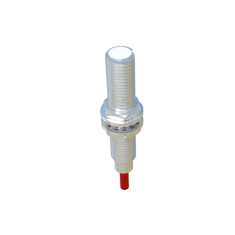
In conclusion, the production of inductive proximity sensors is a symphony of precision mechanics, electromagnetic design, and advanced electronics manufacturing. For the electrical engineer, understanding this process illuminates the sensor's capabilities and limitations, informing better selection for specific applications—whether it's a high-speed counting task demanding a fast response, a washdown environment requiring robust sealing, or a precision assembly process needing minimal hysteresis. The relentless pursuit of miniaturization, intelligence (with integrated diagnostics), and resilience in these manufacturing processes continues to push the boundaries of what automated systems can achieve.