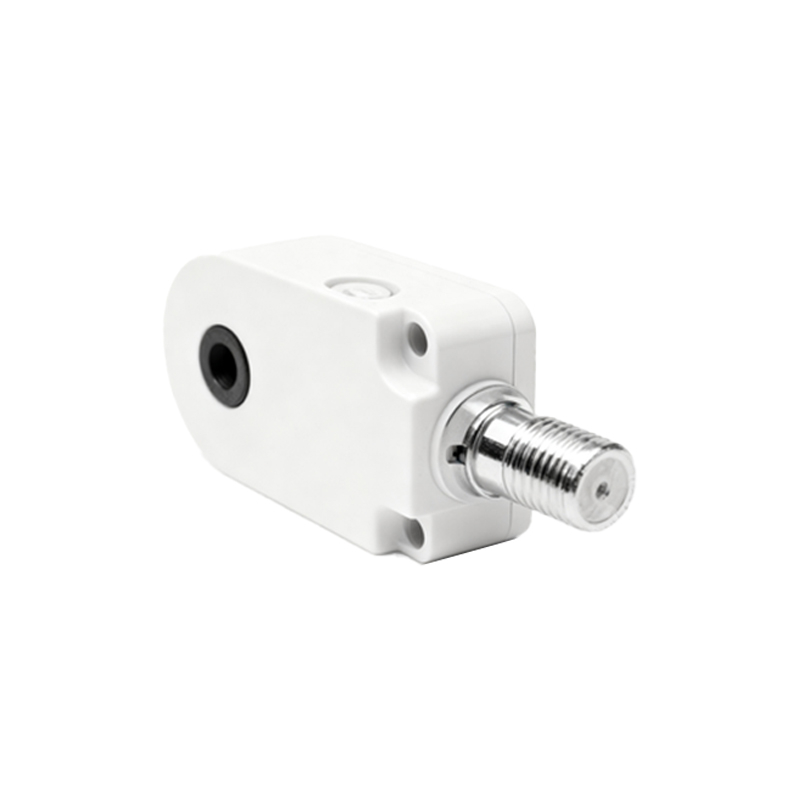
Gear tooth proximity sensors, also known as gear tooth sensors or gear detection sensors, are critical components in modern industrial automation and motion control systems. These non-contact sensors are specifically designed to detect the presence, absence, or speed of gear teeth, providing reliable feedback for precise monitoring and control of rotating machinery. Their robust construction and high accuracy make them indispensable in applications ranging from automotive engine timing and transmission systems to heavy-duty industrial gearboxes and conveyor drives.
The core working principle of a gear tooth proximity sensor is based on electromagnetic induction or the Hall effect, depending on the sensor type. The most common variant is the variable reluctance (VR) sensor, which operates on Faraday's law of electromagnetic induction. A VR sensor consists of a permanent magnet, a pole piece, and a coil of wire wound around the pole piece. As a ferromagnetic gear tooth approaches the sensor's sensing face, it alters the magnetic flux through the coil. When the gear tooth moves closer, the magnetic reluctance decreases, causing an increase in magnetic flux. Conversely, as the tooth moves away, the reluctance increases, and the flux decreases. This changing magnetic flux induces a voltage in the coil—a phenomenon described by Faraday's law. The induced voltage generates a small electrical signal, typically a sinusoidal or near-sinusoidal waveform. The frequency and amplitude of this signal are directly proportional to the gear's rotational speed and the proximity of the tooth. Signal conditioning circuits then process this raw signal into a clean, digital pulse train, where each pulse corresponds to a detected gear tooth. This pulse train can be used by controllers, PLCs, or data acquisition systems to calculate rotational speed, determine angular position, or detect missing teeth for synchronization purposes.
Another prevalent technology is the Hall-effect gear tooth sensor. This type incorporates a Hall-effect IC (integrated circuit) positioned behind a permanent magnet. The Hall IC detects changes in the magnetic field strength caused by the passing gear teeth. As a ferrous gear tooth passes near the sensor, it concentrates the magnetic field lines, increasing the field strength at the Hall element. When a tooth gap passes, the field strength decreases. The Hall IC converts these magnetic field variations into a corresponding digital output signal, usually a square wave. Hall-effect sensors offer advantages such as the ability to detect static (zero-speed) teeth, consistent signal amplitude regardless of speed, and typically a more straightforward interface with modern electronics. Some advanced models integrate signal conditioning, temperature compensation, and protection circuits on a single chip, enhancing reliability in harsh environments.
Key performance parameters for gear tooth sensors include sensing distance (air gap), operating temperature range, frequency response, and output type. The sensing distance is crucial and must be carefully selected based on the gear geometry and installation constraints. An excessively large air gap can weaken the signal, while an overly small gap risks physical contact and damage. These sensors are engineered to withstand extreme conditions common in industrial settings, such as high temperatures, vibration, moisture, and electromagnetic interference. Materials like stainless steel housings and high-temperature-resistant plastics are standard.
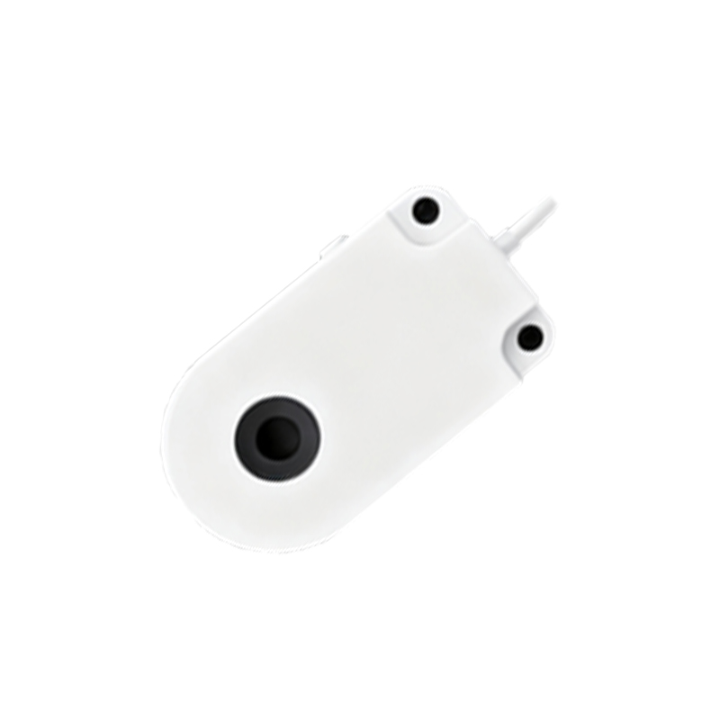
In practical installation, alignment is critical. The sensor must be mounted perpendicular to the gear face and centered on the tooth profile to ensure optimal signal generation and avoid false triggers. The target gear itself must be manufactured with consistent tooth geometry and be made of a ferromagnetic material like steel. Irregularities in the gear, such as damage, wear, or the presence of non-magnetic coatings, can adversely affect sensor performance.
Applications are vast. In automotive engines, these sensors monitor crankshaft and camshaft position, enabling precise fuel injection and ignition timing. In industrial machinery, they provide speed feedback for motor control, synchronize multiple drives, act as overspeed or underspeed safety switches, and facilitate predictive maintenance by detecting irregular rotation patterns indicative of bearing wear or misalignment. Their non-contact nature eliminates mechanical wear, ensuring long service life and minimal maintenance, a significant advantage over mechanical limit switches or encoders in many scenarios.
In summary, gear tooth proximity sensors are sophisticated devices that translate physical motion into actionable electronic data through fundamental electromagnetic principles. Their design prioritizes durability, accuracy, and integration capability, making them a cornerstone of reliable rotational sensing in demanding industrial environments. Proper selection, based on the specific gear characteristics and application requirements, is essential for achieving optimal system performance and longevity.