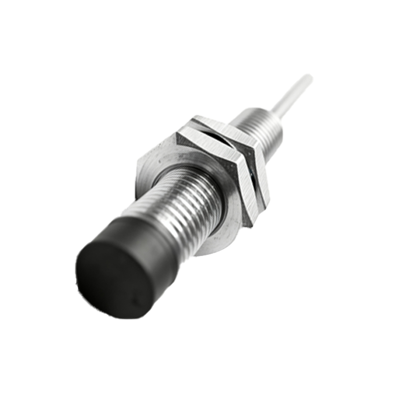
Inductive proximity sensors are widely used in industrial automation for non-contact detection of metallic objects. Understanding their wiring diagrams is crucial for proper installation, operation, and troubleshooting. This article provides a comprehensive guide to inductive proximity sensor wiring, covering common configurations, terminal designations, and practical considerations.
Inductive proximity sensors typically have three or four wires, depending on the output type. The most common types are DC sensors with NPN or PNP transistor outputs. A standard three-wire DC sensor includes wires for power supply positive (brown), power supply negative (blue), and output signal (black). Four-wire sensors often include two output channels (e.g., normally open and normally closed) or an additional diagnostic output.
Wiring diagrams for these sensors follow international color-coding standards (IEC 60947-5-2). For DC sensors, the brown wire connects to the positive DC supply voltage (typically 10-30 VDC), while the blue wire connects to the DC common or ground. The black wire is the switched output. In an NPN configuration, the output transistor connects between the black wire and the blue (negative) wire, sinking current to ground when active. In a PNP configuration, the output transistor connects between the brown (positive) wire and the black wire, sourcing current from the positive supply when active.
When connecting to a programmable logic controller (PLC) or relay, it is essential to match the sensor's output type with the input module. NPN sensors are commonly used with sinking input modules, while PNP sensors pair with sourcing input modules. Incorrect matching can lead to malfunction or damage. Always refer to the sensor's datasheet for specific voltage ratings, current limits, and wiring instructions.
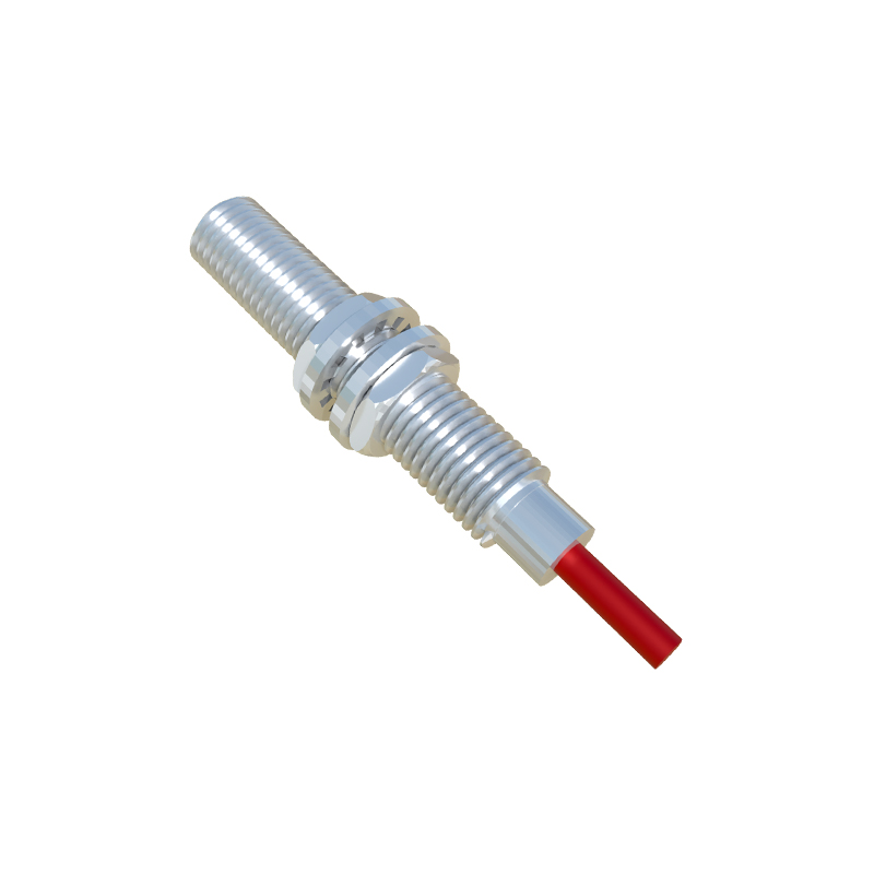
Shielded cables are recommended for long cable runs or electrically noisy environments to prevent electromagnetic interference. The cable shield should be grounded at one end only, typically at the control panel. Additionally, ensure proper wire sizing based on current requirements and distance to avoid voltage drop.
For two-wire AC sensors, wiring is simpler: one wire connects to the AC line voltage, and the other connects to the load. However, these sensors have a residual current when off, which may require a bypass resistor for certain loads like PLC inputs.
Safety precautions are paramount. Always disconnect power before wiring. Verify insulation and secure connections to prevent short circuits. Use conduit or cable carriers in harsh environments to protect against physical damage, moisture, and chemicals.
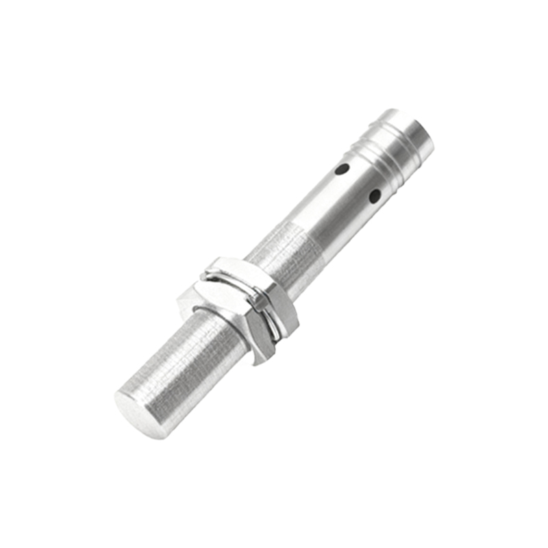
Troubleshooting common wiring issues involves checking power supply voltage, continuity, and output status with a multimeter. If the sensor fails to detect targets, ensure the target material is ferrous (e.g., steel) and within the specified sensing range. Non-ferrous metals like aluminum or copper require sensors with reduced sensing distances.
In summary, correct wiring of inductive proximity sensors ensures reliable operation in automation systems. By adhering to standard diagrams, color codes, and manufacturer guidelines, engineers can optimize performance and longevity. Regular maintenance and inspection further enhance system reliability.