In the field of industrial automation and motion control, proximity angle sensors are indispensable components for precise angular position detection. This article delves into the working principle of these sensors, supported by a detailed explanatory diagram, to provide a clear understanding for engineers and technicians.
Fundamentally, a proximity angle sensor is a type of non-contact position sensor designed to measure the angular displacement or rotation of a shaft. Unlike traditional potentiometers or encoders that may require physical contact, proximity sensors operate by detecting the presence or absence of a target object—typically a metallic or ferrous lobe, gear, or specially shaped rotor—without making direct contact. This non-contact nature eliminates mechanical wear, enhances reliability, and allows for high-speed operation.
The core working principle revolves around electromagnetic or capacitive sensing technologies, with inductive (eddy-current) sensors being the most common for metallic targets. The sensor itself contains an oscillator circuit that generates a high-frequency electromagnetic field at its active face. When a metallic target, such as a rotating lobe on a shaft, approaches this sensing field, eddy currents are induced on the surface of the target. These eddy currents draw energy from the oscillator, resulting in a dampening or reduction of the oscillation amplitude. An evaluation circuit within the sensor monitors this change. The key for angular measurement is the geometric arrangement: as the shaft rotates, the target's profile (like a lobe or a gear tooth) moves in and out of the sensor's detection range. This movement modulates the sensor's output signal.
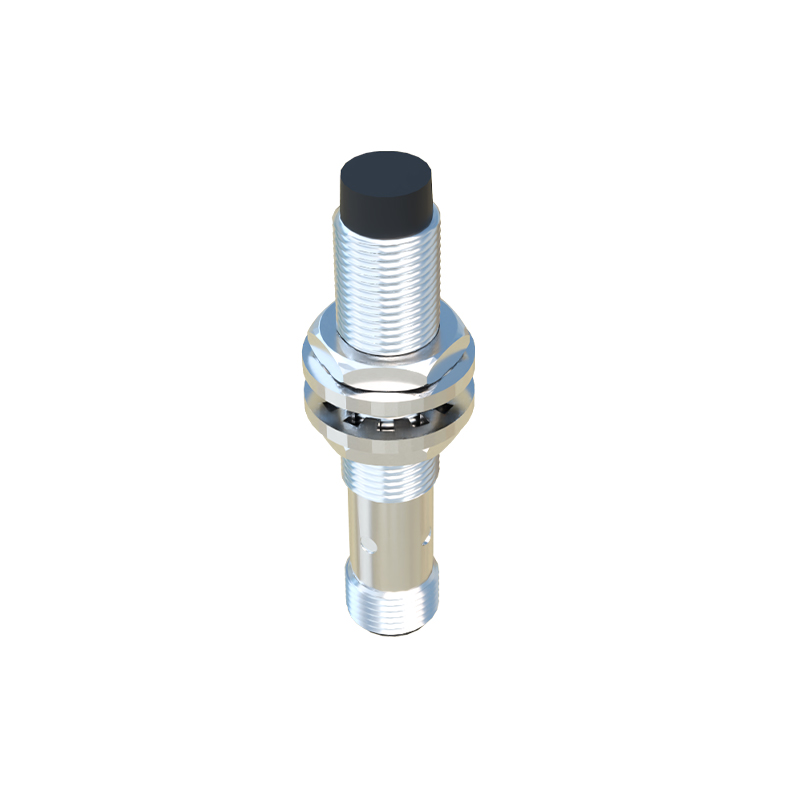
A standard proximity angle sensor setup involves the sensor mounted in a fixed position, facing a rotating target disk attached to the shaft whose angle is to be measured. The target disk is not uniform; it features protrusions, lobes, or teeth. The accompanying principle diagram would illustrate this configuration clearly. The diagram typically shows:
1. The Sensor Body: Housing the oscillator coil, evaluation electronics, and output circuitry.
2. The Sensing Field: Often depicted as a conical or hemispherical zone emanating from the sensor face.
3. The Rotating Target: A disk with one or more lobes or a gear-like structure. The angular position is defined by the lobe's location relative to a reference point.
4. The Output Signal Waveform: A graphical representation showing how the sensor's output (usually a digital ON/OFF signal or an analog voltage/current) changes as the target rotates.
For a single-lobe target, the sensor output might be a single pulse per revolution. By counting these pulses, speed can be measured. For angle measurement, the relationship between the pulse width and the period, or the timing between pulses from multiple sensors, is analyzed. More advanced systems use targets with multiple lobes arranged in a specific pattern (like a coded pattern) or employ two sensors positioned at a known angular offset. By comparing the phase difference between the signals from the two sensors, both the direction and the precise angle of rotation can be determined with high resolution.
The output from these sensors is typically a clean, digital switch signal (PNP/NPN) or a quasi-analog signal proportional to the gap between the target and the sensor face, depending on the design. This signal is then fed into a Programmable Logic Controller (PLC), a motion controller, or a dedicated counter module. The controller processes this timing or pulse data to calculate the exact angular position, speed, and even acceleration of the shaft.
Key advantages of using proximity sensors for angle sensing include robustness in harsh environments (resistant to dust, oil, and vibrations), long operational life due to non-contact operation, and fast response times suitable for high-speed machinery. Common applications are found in automotive systems (e.g., crankshaft and camshaft position sensing), industrial robotics (joint angle limits), conveyor systems, and packaging machinery for registration control.
When interpreting a proximity angle sensor principle diagram, engineers should focus on the sensor's nominal sensing distance (Sn), the target material and size specifications, the hysteresis (the difference between the switch-on and switch-off points), and the output characteristics. Proper installation is critical; the sensor must be mounted securely at the correct distance and alignment to ensure consistent and accurate detection throughout the rotation cycle.
In summary, the proximity angle sensor translates mechanical rotation into an electrical signal by detecting the cyclic variation in the gap between its active face and a specially shaped rotating target. The principle diagram serves as a vital tool for visualizing this interaction, highlighting the non-contact detection zone and the resulting signal modulation that encodes the angular information. Understanding this diagram is essential for proper selection, installation, and troubleshooting of these reliable sensors in modern automated systems.