In industrial automation and control systems, proximity sensors are indispensable components for non-contact detection of objects. Among various types, the 13 series proximity sensors are widely recognized for their robust performance in demanding environments. However, anomalies in these sensors can lead to unexpected machine downtime, production errors, and safety hazards. This article delves into the common causes of 13 proximity sensor malfunctions, systematic diagnostic procedures, and effective corrective solutions, providing a comprehensive guide for maintenance engineers and technicians.
A primary category of anomalies involves false triggering or failure to detect. This often stems from environmental interference. Metallic debris or swarf accumulating near the sensor face can cause erratic behavior, as the sensor may detect this debris instead of the intended target. Similarly, strong electromagnetic interference (EMI) from nearby motors, variable frequency drives (VFDs), or welding equipment can disrupt the sensor's internal oscillator, leading to unreliable output signals. Another frequent culprit is sensor misalignment. Even a slight deviation from the optimal perpendicular alignment to the target can significantly reduce the effective sensing distance, causing intermittent failures.
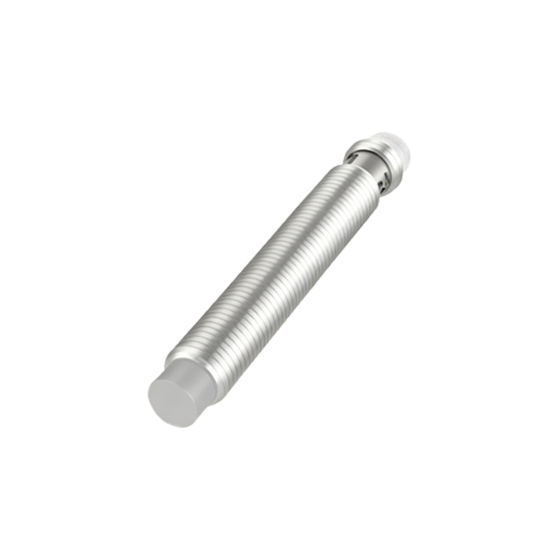
Internal component degradation is another major cause. Over time, the oscillator coil within an inductive proximity sensor can degrade due to thermal cycling or voltage spikes, altering its resonant frequency and sensing characteristics. For capacitive variants, contamination on the sensing face (like oil, grease, or dust) can change the dielectric constant, mimicking the presence of a target. Output stage failures, particularly in solid-state switching elements, can occur due to overcurrent events, such as short circuits in the load wiring. Physical damage, though sometimes obvious, should not be overlooked. Cracks in the housing or epoxy potting can allow moisture ingress, leading to corrosion and circuit failure.
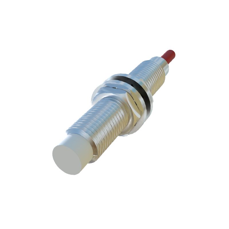
Diagnosing these anomalies requires a methodical approach. The first step is always a visual inspection. Check for physical damage, contamination, correct mounting, and secure electrical connections. Verify the installation specifications: ensure the sensor is within its rated sensing distance (Sn) and that the target material and size are appropriate. A metallic target should be at least equivalent to the sensor's standard target size. Using a multimeter to monitor the output signal while manually triggering the sensor is a fundamental test. For a sinking (NPN) sensor, the voltage between the output wire and the positive supply should drop near zero when activated. For a sourcing (PNP) sensor, the output voltage should rise close to the supply voltage.
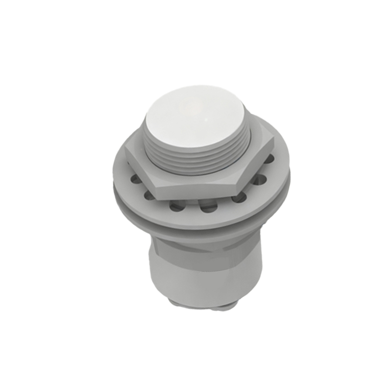
Advanced diagnostics may involve an oscilloscope to observe the stability of the output switching waveform, checking for noise or bounce. Measuring the residual current (leakage current) when the sensor is in the "off" state is crucial for diagnosing output stage issues, as excessive leakage can inadvertently activate a PLC input module. If possible, swapping the suspect sensor with a known-good unit of the same model is one of the most conclusive tests, quickly isolating the problem to the sensor itself or the external circuitry.
Solutions are targeted at the root cause. For environmental issues, selecting a sensor with a higher IP (Ingress Protection) rating, such as IP67 or IP69K, can prevent contamination and moisture damage. Using shielded cables, proper grounding techniques, and installing ferrite cores can mitigate EMI. For alignment problems, adjustable mounting brackets allow for fine-tuning. When internal failure is confirmed, replacement is often the most cost-effective solution. However, consider upgrading to a more robust model, such as one with weld-field immunity for areas near welding operations or all-metal housing for high-vibration environments.
Preventive maintenance is key to minimizing anomalies. Establish a regular schedule for cleaning sensor faces, checking mounting integrity, and verifying electrical connections. Monitor supply voltage stability, as fluctuations outside the sensor's operating range can cause premature failure. Keep a log of sensor failures to identify patterns or problematic locations in the system.
In conclusion, 13 proximity sensor anomalies, while disruptive, are typically diagnosable and solvable with a structured approach. Understanding the common failure modes—environmental interference, misalignment, and internal degradation—empowers engineers to perform efficient troubleshooting. By combining basic electrical checks with environmental assessments and implementing robust installation practices, the reliability of these critical sensing components can be maximized, ensuring smooth and continuous operation of automated industrial systems.