In industrial automation and control systems, proximity sensors are indispensable components for non-contact detection of objects. Their reliability is paramount for maintaining continuous production and preventing costly downtime. A common failure mode for these sensors is burning out, often resulting from electrical overload, short circuits, improper wiring, or environmental stressors. Unlike mechanical failures, a burnt-out sensor may not always present obvious physical damage, making diagnosis a critical skill for maintenance engineers and technicians. This guide details systematic methods to determine if a proximity sensor is burnt out.
The first and most immediate step is a visual inspection. While a burnt sensor might not always show external signs, look for tell-tale indicators such as discoloration on the sensor housing (often brown or black), a cracked or melted lens or body, charred wiring at the connection points, or a distinct burnt odor emanating from the device. Any visible signs of overheating, like bubbling or warping of plastic components, strongly suggest internal damage from excessive current. However, the absence of visual cues does not rule out an electrical burnout, necessitating further electrical testing.
Electrical testing forms the core of the diagnostic process. Begin by ensuring the system is safely locked out and de-energized. Using a digital multimeter (DMM), perform these checks:
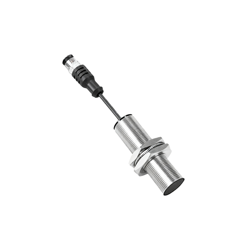
1. Continuity/Resistance Check: Disconnect the sensor from the circuit. Set your DMM to the resistance (Ohms) setting. For a typical 3-wire DC sensor (Brown+/Blue-/Black output), measure the resistance between the power supply terminals (often between Brown+ and Blue-). A healthy sensor typically shows a relatively high resistance (often in the kilo-ohm range, but consult the datasheet). A reading of very low resistance (near zero Ohms) or an open circuit (infinite resistance, OL) indicates a likely short circuit or open internal component, respectively—both signs of burnout. For 2-wire sensors, check resistance between the two wires; similar principles apply.
2. Diode Test (for DC Sensors): Some DMMs have a diode test function. On a disconnected 3-wire DC sensor, you can test between the Brown (+) and Black (output) wires, and then reverse the probes. A functioning output transistor (typically a sinking or sourcing NPN/PNP) will show a voltage drop in one direction (e.g., 0.4V to 0.7V) and an open circuit (OL) in the other. Readings of OL in both directions or a very low drop (like 0.1V) in both directions suggest a burnt-out output stage.
3. Power-Up Output Test: This is a live test and must be performed with caution. Reconnect the sensor to its correct power supply as per its specifications (e.g., 10-30V DC). Use your DMM in voltage mode. Measure the voltage between the output wire (Black) and the negative supply (Blue). For a normally-open (NO) sensor, the output voltage should be near the supply voltage when no target is present and drop to near 0V (for a sinking sensor) when a valid target is within the sensing range. A burnt sensor may show incorrect behavior: the output might be stuck high (at supply voltage) regardless of target presence, stuck low (near 0V), or fluctuate erratically. An output that does not change state with target presence is a strong indicator of failure.
4. Current Draw Measurement: Using a clamp meter or DMM in series, measure the sensor's current consumption. Compare the reading to the quiescent current specified in the sensor's datasheet. A current draw significantly higher than specified, especially under no load, often indicates an internal short circuit due to burnout. Conversely, a reading of zero amperes suggests an open circuit.
Beyond basic electrical tests, consider the operational context. A sensor suspected of being burnt out should be examined within its system. Check the associated PLC input module's status indicator. If the input LED remains off or on constantly when the sensor's target is moved, while other sensors on the same module work correctly, it points to a sensor issue. Also, inspect the wiring harness for insulation damage, crushed cables, or loose connections that could have caused a short circuit leading to the burnout. Verify that the load (e.g., the PLC input) is within the sensor's rated switching capacity; driving an excessive load is a common cause of output stage failure.
Environmental factors are frequent contributors to premature failure. Exposure to excessive moisture, conductive dust, corrosive chemicals, or extreme temperatures can degrade internal components and lead to electrical failure that manifests as burnout. Even if a sensor passes a basic bench test, a history of operating outside its specified environmental ratings can cause intermittent failures