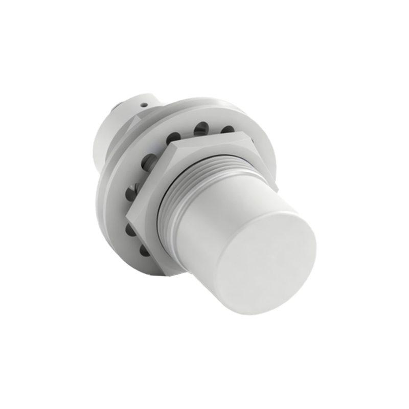
Proximity sensors are indispensable components in modern hydraulic press systems, serving as the primary interface for detecting the position of rams, tooling, and workpieces. Their reliable operation is critical for ensuring cycle accuracy, preventing collisions, and maintaining overall system safety. However, like all electronic components in an industrial environment, they are susceptible to various failure modes. Understanding these failures and implementing effective troubleshooting strategies is paramount for minimizing downtime and ensuring consistent production quality.
One of the most prevalent failure categories involves physical and environmental damage. Hydraulic press environments are notoriously harsh, characterized by significant vibration, shock loads, oil mist, metal chips, and coolant spray. Physical impact from misaligned tooling or ejected parts can crack sensor housings or damage the sensing face. Even minor accumulations of ferrous debris on an inductive sensor's active surface can attenuate its sensing field, leading to inconsistent or failed detection. Similarly, conductive swarf can cause erroneous triggering. Environmental seals can degrade over time, allowing hydraulic oil or coolant to infiltrate the sensor body, leading to internal short circuits or corrosion of electronic components. Extreme temperatures, either from ambient conditions or radiated heat from the hydraulic system, can also push sensors beyond their specified operating ranges, causing drift in switching points or complete failure.
Electrical issues constitute another major source of problems. Wiring faults are common; these include broken wires due to constant flexing in cable carriers, loose connections at terminal blocks, or damaged insulation leading to short circuits. Electrical noise is a significant concern, especially from high-power solenoids, variable frequency drives (VFDs) controlling pump motors, or welding equipment nearby. This electromagnetic interference (EMI) can induce false signals in sensor cables, causing erratic behavior. Power supply problems, such as voltage spikes, sags, or ripple, can also destabilize sensor performance. Furthermore, incorrect sensor selection—such as using a standard 2-wire DC sensor in a circuit with high leakage current, or mismatching the sensor's output type (PNP vs. NDC) with the PLC input card—will result in immediate malfunction.
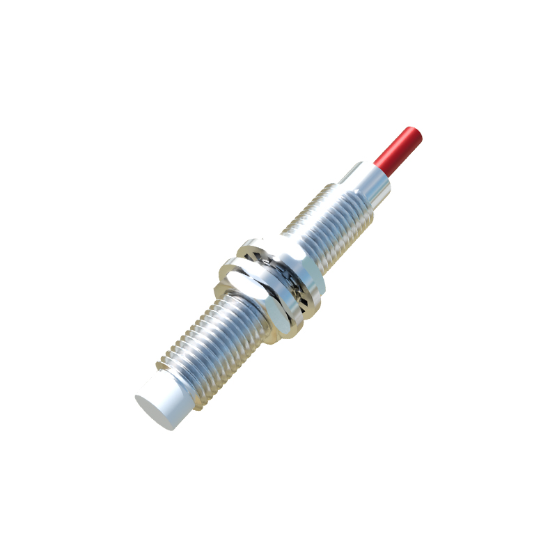
Sensor-specific performance degradation also occurs. The sensing distance of inductive and capacitive sensors can diminish over time due to aging electronic components or temperature effects. For example, a sensor rated for an 8mm range may effectively only sense at 6mm after prolonged use, causing missed detections if the target is positioned at the limit. Wear and tear on the target itself—such as a flag on a moving platen becoming dented, corroded, or coated with buildup—can similarly reduce the effective sensing distance. For ultrasonic or photoelectric sensors used in certain press applications, contamination of the lens or transducer by oil film or dust will scatter or absorb the signal.
A systematic troubleshooting approach is essential for rapid diagnosis. The process should always begin with a visual and mechanical inspection. Power down the system, lock out/tag out (LOTO), and physically examine the sensor for obvious damage, misalignment, or contamination. Check the target's condition and its travel path to ensure it passes consistently within the sensor's nominal range. Verify all mechanical fasteners are tight to prevent vibration-induced issues.
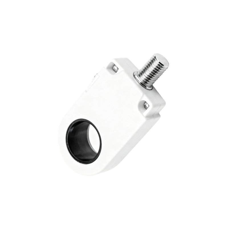
Next, proceed to electrical verification. Using a multimeter, check the supply voltage at the sensor terminals under load to confirm it is within the specified range (e.g., 24VDC ±10%). For a 3-wire DC sensor, monitor the output voltage relative to the common wire when a target is presented and removed. A PNP sensor should switch between a high state (near supply voltage) and a low state (near 0V). An NPN sensor does the opposite. For 2-wire AC/DC sensors, measure the voltage drop across the sensor or use a clamp meter to check current flow. Signal monitoring with an oscilloscope is the most definitive electrical test, as it can reveal noise, contact bounce, or slow switching that a multimeter might miss. Always inspect the entire cable run for damage and ensure conduit entries are sealed.
If the sensor itself is suspected, the simplest test is substitution with a known-good unit of identical specifications. Before installing the new sensor, ensure its operating parameters (sensing distance, output type, voltage) match the application requirements. Many modern sensors have LED indicators that provide crucial status information; a solid or blinking LED can indicate power, output state, or error conditions like short-circuit protection activation.
Preventive maintenance is key to avoiding unscheduled stops. Establish a regular schedule to clean sensor faces and inspect for physical damage. Use sensors with appropriate ingress protection (IP67 or higher is typical for press environments) and correct housing materials (e.g., stainless steel for washdown or corrosive areas). Ensure proper mounting using rigid brackets to minimize vibration, and employ shielded cables with the shield properly grounded at the control panel end only