Accurate measurement of laser sensor pins is a fundamental yet critical task for electrical engineers, technicians, and anyone involved in system integration or maintenance. Laser sensors, pivotal in applications ranging from industrial automation to precision metrology, rely on correct pin configuration for power, signal output, and communication. Incorrect handling can lead to sensor malfunction, inaccurate readings, or even permanent damage. This guide provides a systematic, industry-standard approach to measuring and verifying laser sensor pinouts.
Before initiating any measurement, paramount importance must be placed on safety. Always disconnect the sensor from its power source and control system. Allow capacitors to discharge fully if the sensor was recently powered. Refer to the manufacturer's datasheet—the definitive source for pin definitions, voltage ratings, and signal types. Gather the necessary tools: a high-quality digital multimeter (DMM) with diode test and continuity functions, fine-point probe tips, a stable DC power supply for bench testing if required, and the sensor's connector diagram.
The initial step involves a thorough visual inspection. Examine the sensor's connector housing for any labels indicating pin numbers (e.g., 1, 2, 3) or standard markings (V+, V-, OUT, GND). Note the connector type (e.g., M8, M12, D-sub) as this often correlates with common industry pinouts. Clean the connector pins carefully to remove any oxidation or debris that could affect measurements.
Resistance and continuity checks form the core of passive measurement. Set your DMM to the continuity or resistance (Ω) mode. Identify the presumed ground (GND) pin, often connected to the sensor's metal housing or shield. Verify this by placing one probe on the housing (ensure a clean contact point) and the other on the pin; a low resistance reading (near 0 Ω) or an audible beep confirms a ground connection. Next, check for short circuits between adjacent pins that should be isolated. Any unexpected low resistance here indicates a potential internal fault.
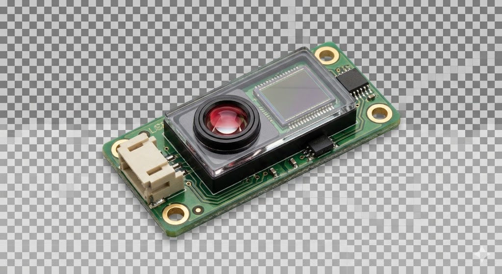
For sensors with multiple signal outputs (e.g., NPN/PNP open collector, push-pull), measuring the output pins requires understanding their state. A common method involves applying the correct operating voltage (e.g., 12-24V DC) between the V+ and GND pins, strictly following datasheet limits. With power applied, use the DMM in voltage DC mode. Measure the voltage between the signal output pin and GND. The reading will depend on the output type and state. For a digital output, it may read near 0V (low) or near the supply voltage (high), depending on the target presence and sensor logic. Analog output pins (e.g., 0-10V, 4-20mA) require a precise load (like a resistor for current loops) and will show a variable voltage proportional to the measured distance.
The diode test function of a DMM is invaluable for identifying polarity-sensitive components within the sensor's output stage, such as protection diodes. By applying a small test current, you can determine the forward voltage drop across junctions, helping to map out internal circuitry connected to the pins.
For advanced sensors with serial communication (IO-Link, RS-422), pin measurement moves beyond simple voltage checks. You will need an oscilloscope to analyze signal waveforms on the data lines. Look for characteristic communication pulses when the sensor is powered and connected to a compatible master. The absence of a clean digital signal on the designated pin, while power and ground are confirmed, suggests a communication interface issue.
Always document your findings. Create a pinout table listing the pin number, your measured function (e.g., GND: 0Ω to housing, V+: 24V input, OUT: 12V when target absent), and compare it against the datasheet. Discrepancies must be investigated. Common pitfalls include assuming standard pinouts without verification, using a multimeter with low input impedance affecting sensitive analog readings, and neglecting the sensor's required load for current outputs.
In conclusion, methodical measurement of laser sensor pins is not merely about checking connections; it is a diagnostic process that validates sensor integrity and ensures seamless system integration. By adhering to a disciplined sequence—safety first, datasheet consultation, visual inspection, passive checks, followed by active powered measurements—engineers can confidently verify pin functionality, troubleshoot issues, and guarantee the reliable operation of these precise optical devices in any application.