Proximity sensors are fundamental components in modern industrial automation, robotics, and countless electronic systems. Their ability to detect the presence or absence of an object without physical contact makes them indispensable. While much focus is placed on sensor types (inductive, capacitive, photoelectric, ultrasonic), the underlying circuit components that bring these sensors to life are equally critical. This article delves into the essential electronic components that constitute a typical proximity sensor circuit, explaining their roles and interplay.
At the heart of most active proximity sensors lies an oscillator circuit. This circuit generates a high-frequency electromagnetic field (for inductive sensors) or an electrostatic field (for capacitive sensors). Key components here include an inductive coil or capacitive plate (the sensing element itself), along with supporting capacitors and inductors that determine the oscillation frequency. A transistor, often a MOSFET or bipolar junction transistor, acts as the switching element to sustain oscillations. The stability of this oscillator is paramount; any disturbance caused by a target object entering the sensing field alters the oscillation's amplitude or frequency.
The signal from the oscillator is weak and needs processing. This is where the amplifier circuit comes in. Composed typically of operational amplifiers (op-amps) or discrete transistors arranged in common-emitter or common-collector configurations, this stage boosts the minute change in the oscillator's signal to a usable level. Precision resistors and capacitors around the op-amp set the gain and bandwidth, ensuring the circuit responds only to the desired frequency range and ignores noise.
Following amplification, the signal enters the detector or demodulator circuit. This stage converts the alternating (AC) signal from the oscillator into a direct (DC) voltage. Diodes, specifically Schottky diodes for their low forward voltage drop and fast switching, are commonly used in simple peak detector configurations. RC filter networks (resistors and capacitors) smooth the rectified signal, removing residual AC ripple to produce a clean DC voltage that is proportional to the amplitude of the original oscillation.
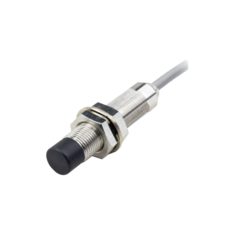
The clean DC signal then feeds into a comparator circuit. This is the decision-making unit of the sensor. A comparator, often a dedicated IC like the LM393 or an op-amp configured without feedback, compares the processed sensor signal against a predefined reference voltage. This reference is set by a voltage divider network consisting of fixed or adjustable potentiometers and resistors. When the sensor signal exceeds (or drops below) this threshold, the comparator's output switches state, indicating target detection.
The output stage interfaces the sensor with the external control system (e.g., a PLC). For a simple digital output, a switching transistor (like a BJT or a MOSFET) is driven by the comparator's output. This transistor acts as a solid-state switch to control the current through the output terminal. For protection, flyback diodes are crucial when driving inductive loads (like relays) to suppress voltage spikes. Current-limiting resistors protect the output transistor from overcurrent conditions. In more advanced sensors, output driver ICs or solid-state relays provide robust, isolated switching capabilities.
Power management is vital. Most industrial sensors operate on a wide range of DC voltages (e.g., 10-30V DC). A voltage regulator IC, such as a 78-series linear regulator or a more efficient switching regulator, provides stable, low-noise voltage (e.g., 5V or 3.3V) for the sensitive oscillator, amplifier, and comparator circuits. Decoupling capacitors (both electrolytic and ceramic) are placed near every IC's power pin to filter high-frequency noise and ensure stable operation. Transient voltage suppression (TVS) diodes or varistors at the power input端子 protect the entire circuit from voltage surges and electrostatic discharge (ESD).
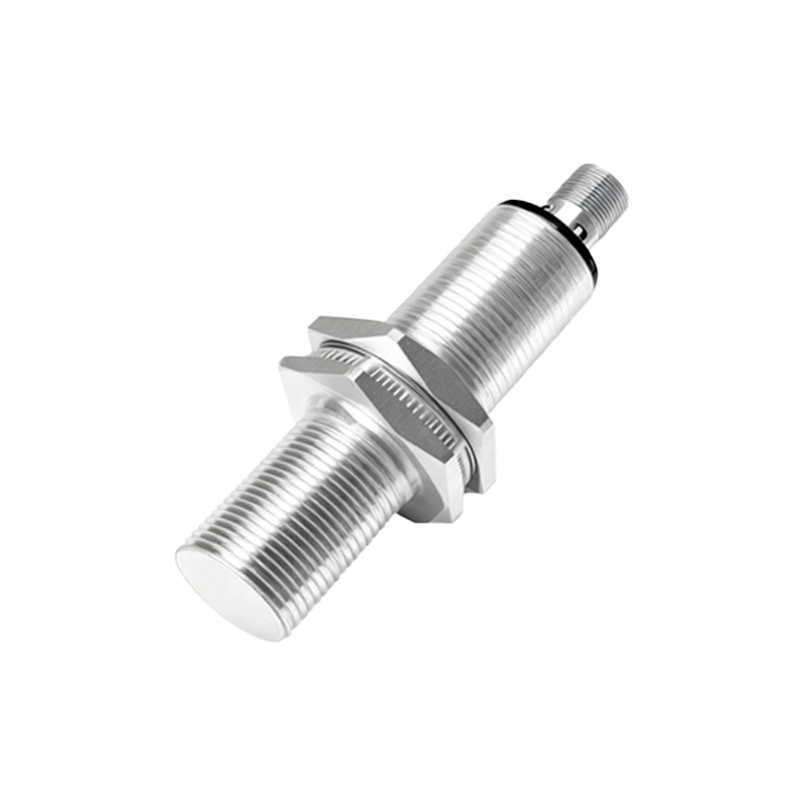
Finally, the entire assembly is influenced by passive components: resistors for biasing and setting thresholds, capacitors for filtering and timing, and inductors for frequency tuning. The quality and temperature stability of these components, especially in the oscillator tank circuit, directly affect the sensor's sensitivity, repeatability, and temperature drift.
In summary, a proximity sensor is a sophisticated symphony of discrete and integrated circuits. From the oscillator generating the sensing field to the robust output stage, each component—from the humble resistor to the complex op-amp—plays a deliberate role. Understanding this circuitry empowers engineers to select, troubleshoot, and integrate these sensors more effectively, ensuring reliable performance in demanding industrial environments.