In industrial automation and control systems, proximity sensors are indispensable components for non-contact object detection. Among the various models, the BN series is widely recognized for its reliability and versatility. A correct understanding of the proximity sensor wiring diagram BN is fundamental to ensuring optimal performance, safety, and system integration. This article provides a detailed technical breakdown of the standard wiring configurations for a typical 3-wire DC BN-type proximity sensor, which is the most common variant in industrial settings.
A standard 3-wire DC proximity sensor, such as many in the BN family, features three distinct wires, each color-coded for universal identification: Brown, Blue, and Black. The brown wire is universally designated for the positive supply voltage (+V). This wire must be connected to the positive terminal of the DC power source. The voltage range is typically between 10-30V DC, but it is crucial to consult the specific sensor's datasheet for exact specifications. The blue wire is the common negative or ground wire (0V). It must be connected to the negative terminal of the DC power supply and often also to the system ground to ensure a stable reference potential and minimize electrical noise.
The functionality of the sensor is determined by the third wire, which is usually black. This is the output signal wire. There are two primary output types: NPN (sinking) and PNP (sourcing). The wiring diagram differs significantly between these two types. For an NPN output sensor, the black wire provides a switched negative connection. In its normal state (no target detected), the output is effectively open. When a target enters the sensing range, the internal NPN transistor switches ON, connecting the black wire to the internal ground (blue wire). This "sinks" current to ground, typically completing a circuit to a PLC input module or relay that is internally pulled up to the positive supply. The load (e.g., PLC input) is connected between the positive supply (+V) and the black wire.

Conversely, for a PNP output sensor, the black wire provides a switched positive connection. In its normal state, the output is open. Upon target detection, the internal PNP transistor switches ON, connecting the black wire to the internal positive supply (brown wire). This "sources" current from the sensor. Here, the load is connected between the black wire and the ground (0V). Misidentifying the output type and wiring it incorrectly is a common installation error that will prevent the sensor from functioning and could potentially cause damage.
Beyond the basic three wires, some BN series sensors may include an additional wire, often white or another color, which serves as a complementary output or a diagnostic output. Always refer to the manufacturer's specific wiring diagram printed on the sensor body or provided in the technical manual. Key steps for a successful installation include: First, verifying the sensor type (NPN/PNP) and supply voltage. Second, ensuring the power is disconnected before starting any wiring work. Third, using proper cable management and shielding, especially in environments with high electromagnetic interference (EMI). Fourth, paying close attention to the load current rating of the sensor output to avoid overloading the transistor. Finally, for 2-wire AC/DC sensors (less common in BN series), the wiring is simpler, with the two wires acting in series with the load and power supply, but polarity must be observed for DC versions.
Troubleshooting often begins with the wiring diagram. Common issues include no output signal, which may stem from incorrect power supply polarity, voltage mismatch, or a miswired load for the output type. Intermittent operation can be caused by loose connections, insufficient shielding, or electrical noise from nearby high-power equipment. Ensuring proper grounding of the sensor housing and the system, as well as maintaining the recommended sensing distance free from obstructions and contaminants like metal dust or oil, is critical for long-term reliability.
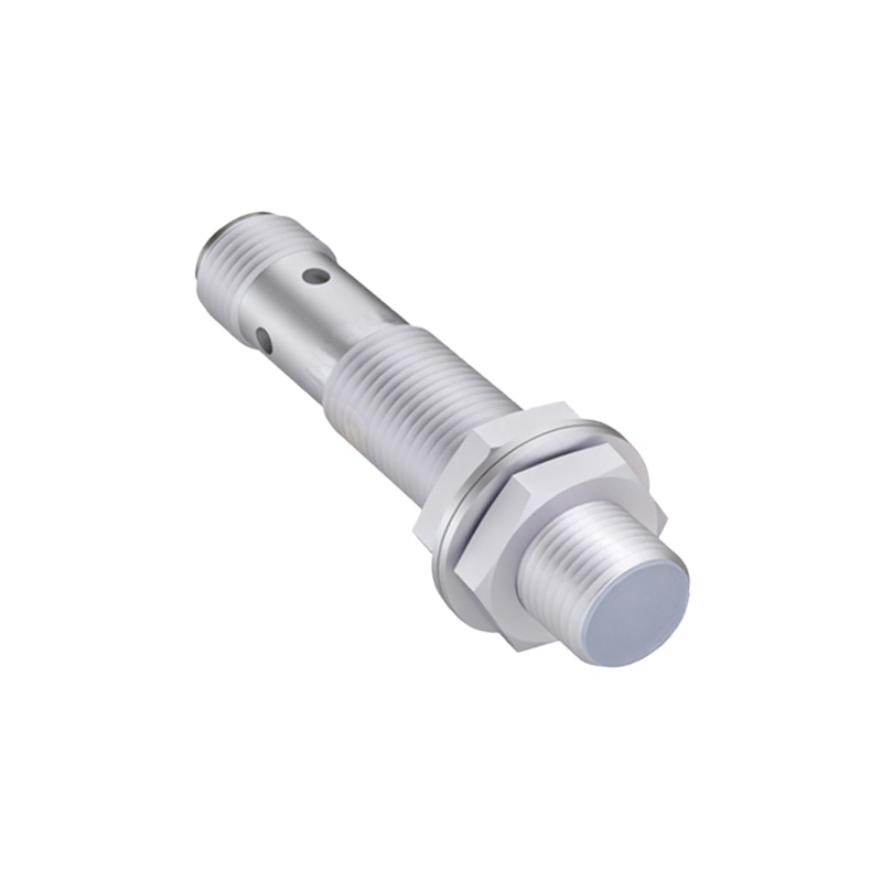
In conclusion, the proximity sensor wiring diagram BN is not merely a connection guide but a blueprint for reliable operation. A meticulous approach to wiring, grounded in a clear understanding of the color codes and output logic (NPN vs. PNP), is essential for any electrical engineer or technician. Proper installation, as dictated by the correct diagram, directly impacts the sensor's response time, accuracy, and service life, forming a robust foundation for any automated control system.