In the dynamic landscape of industrial automation and control system design, engineers are frequently tasked with modifying or upgrading existing installations. One common scenario involves the conversion of proximity sensors to traditional push button switches. This transition, while seemingly straightforward, requires a nuanced understanding of both technologies, their operational principles, and the implications for the overall control circuit. This article provides a comprehensive, practical guide for electrical engineers undertaking such a modification, focusing on the technical rationale, procedural steps, and critical considerations.
Proximity sensors, whether inductive, capacitive, or photoelectric, are non-contact devices that detect the presence or absence of an object within their sensing field. They output a discrete signal, typically a change in voltage state (e.g., 24V DC sinking or sourcing), to a Programmable Logic Controller (PLC) or other control unit. Their primary advantages include high reliability, long service life (due to lack of physical contact), and suitability for harsh environments. However, there are instances where a manual, tactile interface is preferable or necessary. These include maintenance overrides, manual testing sequences, operator intervention points, or situations where the original sensed object is no longer present or reliable. In such cases, replacing a proximity sensor with a push button switch becomes a viable solution.
The core of the conversion lies in interfacing the mechanical switch with the existing sensor's electrical footprint. The first step is a thorough circuit analysis. Identify the sensor's specifications: its supply voltage (commonly 10-30V DC), output type (PNP-sourcing or NPN-sinking), and wiring configuration (2-wire, 3-wire, or 4-wire). A standard maintained or momentary push button switch does not inherently have this polarity or configuration; it is a simple mechanical contact. Therefore, the existing sensor's power supply and signal wiring must be adapted.
For a typical 3-wire DC sensor, the conversion process generally follows these steps:
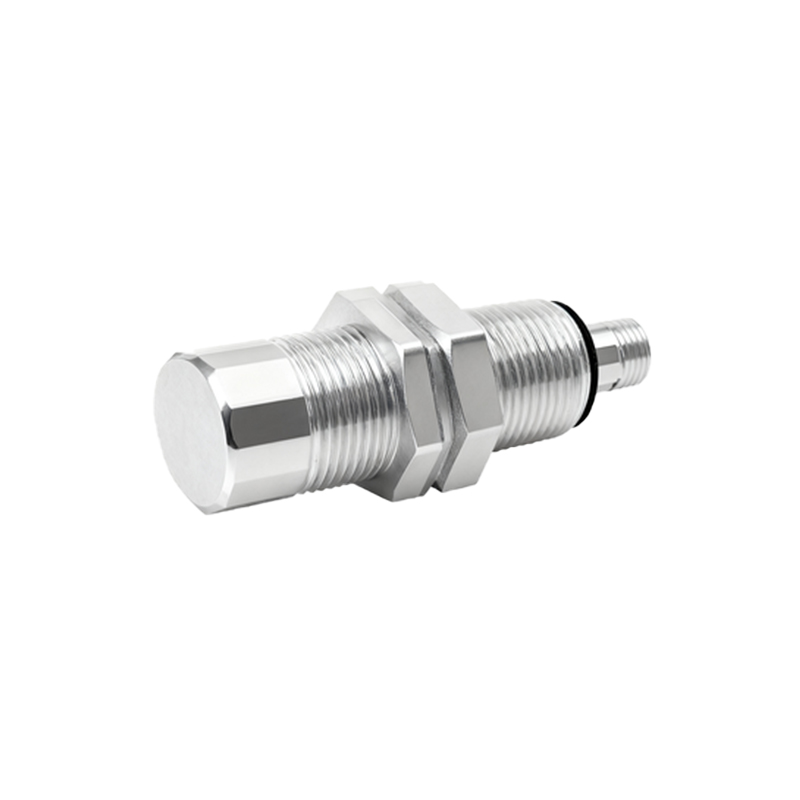
1. De-energize and Lock Out/Tag Out (LOTO): This is the paramount safety step. Isolate and secure all power sources to the control panel and the sensor circuit.
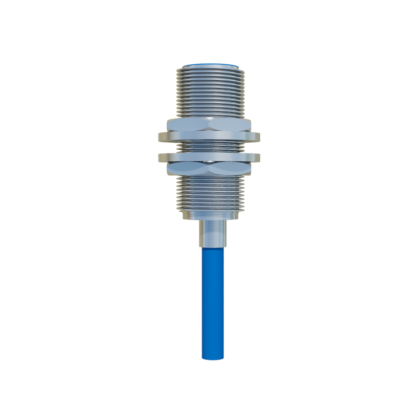
2. Remove the Proximity Sensor: Disconnect the wiring from the sensor terminals. Note the wire colors or labels connected to the positive supply (e.g., brown), negative/0V (e.g., blue), and signal output (e.g., black).
3. Select an Appropriate Push Button: Choose a switch rated for the control voltage and current. A standard industrial push button with a Normally Open (NO) or Normally Closed (NC) contact block is sufficient. The choice between maintained (latching) and momentary action depends on the desired control logic.
4. Rewire to the Push Button Station: The key is to use the existing power supply to create a switched signal.
Connect the positive supply wire (e.g., brown) to one terminal of the push button's contact.
Connect the other terminal of the push button's contact to the wire that originally went to the sensor's signal output (e.g., black).
The negative/0V supply wire (e.g., blue) must remain connected to the PLC input's common terminal. Crucially, do not connect the switch directly between positive and negative supply, as this would create a short circuit when pressed. The switch is placed in series with the signal line.
5. PLC/Logic Reconfiguration: Physically, the wiring now simulates an active-high (for PNP systems) signal when the button is pressed. However, the PLC logic programmed for the sensor input may need review. Logic originally written for a proximity sensor that activates when an object is present will now activate when the button is pressed. This is usually acceptable, but if the original logic used the sensor's "off" state for a critical function, the program may require adjustment, or an NC push button contact should be used.
Several critical considerations must be addressed:
Sourcing vs. Sinking: The above example assumes a PNP (sourcing) sensor. For an NPN (sinking) sensor, the wiring logic is inverted. The push button would be wired to switch the connection to the 0V/negative line. Misunderstanding this will result in a non-functional circuit.
Sealing and Environment: Proximity sensors are often sealed (IP67). The push button enclosure must provide an equivalent or adequate ingress protection rating for the installation environment.
Functionality Loss: The automatic, hands-free operation is lost. Ensure this manual intervention is acceptable for the process.
Documentation: Update all electrical schematics, panel layouts, and maintenance manuals to reflect the change from a "Proxim