In modern industrial automation, precise motor control is paramount for efficiency, safety, and process optimization. One of the most effective methods for achieving this involves the integration of analog proximity sensors with Variable Frequency Drives (VFDs). This combination enables sophisticated, responsive, and energy-efficient control of AC motors based on real-time physical measurements.
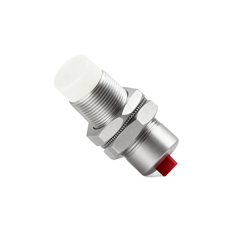
An analog proximity sensor, unlike its digital counterpart which provides a simple on/off signal, outputs a continuous voltage or current signal proportional to the distance to a target object. Common output ranges are 0-10V DC or 4-20mA. This analog signal carries rich information about the position, presence, or even the rate of approach of an object within its sensing range. When this signal is fed into the analog input of a VFD, it becomes a powerful command variable.
The VFD, the workhorse of motor control, varies the frequency and voltage supplied to an AC motor, thereby controlling its speed and torque. Most industrial-grade VFDs are equipped with multiple analog input terminals configurable for voltage or current signals. These inputs are typically assignable to various control functions, with the most common being speed reference or frequency command.
The implementation process begins with sensor selection and mounting. The analog proximity sensor must be chosen based on the required sensing distance, target material, environmental conditions (temperature, contaminants), and the necessary output signal type. Proper installation is critical to ensure a stable and linear output corresponding to the actual distance variation.
The heart of the system lies in the VFD parameter configuration. The key steps involve:
1. Input Configuration: Setting the specific analog input (e.g., AI1) to accept either a 0-10V or 4-20mA signal, matching the sensor's output.
2. Scaling: Defining the relationship between the input signal and the desired motor output. For instance, you might configure the VFD so that 0V (or 4mA) corresponds to 0 Hz (motor stop) and 10V (or 20mA) corresponds to 60 Hz (motor at full speed). This scaling can be linear or, through advanced function blocks, follow a custom curve.
3. Function Assignment: Assigning the scaled analog input value as the primary speed reference source for the drive.
4. Tuning Response: Adjusting acceleration/deceleration ramps and filter settings on the analog input to smooth out signal noise and prevent abrupt motor speed changes, ensuring stable operation.
A classic application is in conveyor belt speed regulation. An analog sensor positioned to measure the height of material on a conveyor (e.g., in a hopper or at a transfer point) can send a signal to the VFD controlling the conveyor motor. As the material level rises, the sensor output increases, commanding the VFD to slow the conveyor, preventing overflow. Conversely, a low level signals the VFD to increase speed for optimal material flow. This creates a closed-loop control system that maintains process consistency without manual intervention.
Other prevalent applications include:
Web Tension Control: In winding/unwinding systems, a dancer arm equipped with a position sensor provides an analog signal to the VFD to maintain constant material tension.
Pump Pressure/Flow Control: A pressure transducer's 4-20mA signal can directly command a pump VFD, varying motor speed to maintain a set pressure, significantly saving energy compared to throttling valves.
Positioning Systems: While not for high-precision servo applications, simple positioning tasks, like stopping a lift at a floor based on a sensor reading, are efficiently handled by this setup.
The benefits are substantial. This method offers continuous and precise control, allowing for infinite speed variations within the set range. It enhances system responsiveness, as the motor speed adjusts instantly to changes detected by the sensor. From an energy perspective, it is highly efficient, as the motor runs only at the speed necessary for the current condition, reducing power consumption. The system architecture is simplified by eliminating the need for a separate programmable logic controller (PLC) for basic control loops, reducing cost and complexity.
However, engineers must consider certain limitations. Analog signals are susceptible to electrical noise from motors and power lines, necessitating proper shielding, grounding, and sometimes signal isolators. The linearity and accuracy of the sensor directly impact control precision. Furthermore, the configuration requires a solid understanding of both sensor characteristics and VFD parameterization.
In conclusion, the direct control of a Variable Frequency Drive using an analog proximity sensor represents a elegant and powerful solution for numerous industrial automation scenarios. It embodies the principle of using a direct physical measurement to dictate a primary process variable—motor speed. By mastering the selection, installation, and parameterization of both components, automation engineers can design