Inductive proximity switches are widely used in industrial automation for non-contact detection of metallic objects. Understanding the correct wiring diagram is crucial for ensuring reliable operation and system safety. This guide provides a detailed overview of the physical wiring connections for typical inductive proximity sensors, covering common configurations, terminal designations, and practical installation tips.
Most inductive proximity sensors feature three or four wires, depending on the output type. The standard three-wire sensors include a brown wire (positive supply), a blue wire (negative supply or ground), and a black wire (output signal). For DC sensors, the brown wire connects to the positive DC voltage (typically 10-30 VDC), the blue wire to the negative or ground, and the black wire to the load (such as a PLC input or relay). In four-wire versions, an additional white wire may serve as a complementary output or diagnostic signal. Always refer to the manufacturer's datasheet for specific wire color codes, as variations exist between brands and regions.
Wiring diagrams typically illustrate connections to power sources and control devices. For example, a common NPN (sinking) output sensor connects the black wire to the load, which is then linked to the positive supply, while the load's other side ties to the negative. Conversely, PNP (sourcing) output sensors connect the black wire directly to the load, with the load's opposite side linked to ground. It's essential to match the sensor's output type with the control system's input requirements to avoid malfunctions. Shielding and grounding practices should be followed to minimize electrical noise interference, especially in environments with motors or frequency drives.
Installation considerations include maintaining proper clearance between the sensor and metal surfaces to prevent false triggering. Sensors should be mounted securely, with cables routed away from high-voltage lines to reduce electromagnetic interference. For long cable runs, use twisted-pair cables and ensure voltage drop does not exceed the sensor's operating range. Testing the wiring with a multimeter before full system activation can help identify issues like short circuits or incorrect polarities.
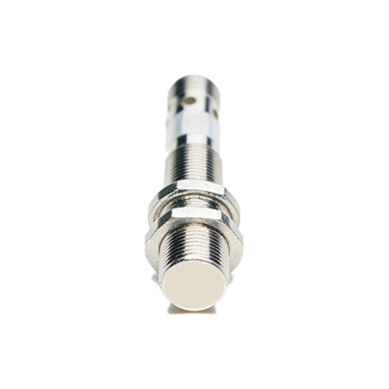
In summary, correct wiring of inductive proximity switches hinges on understanding wire functions, output types, and environmental factors. Adhering to standardized diagrams and manufacturer guidelines ensures optimal performance, longevity, and safety in automated systems. Regular maintenance checks, such as inspecting cable integrity and connection tightness, further enhance reliability. By mastering these wiring principles, engineers can effectively integrate these sensors into diverse industrial applications, from conveyor systems to robotic assemblies.