Proximity sensors are indispensable components in modern industrial automation, providing non-contact detection of metallic and, in some cases, non-metallic objects. Their reliability is crucial for process continuity, machine safety, and quality control. However, like all electronic devices, they are susceptible to various faults that can trigger error codes or cause system malfunctions. This article outlines common proximity sensor failure modes, diagnostic procedures, and corrective actions, presented from an engineering perspective.
A primary category of faults involves incorrect or inconsistent sensing. The sensor may fail to detect a target within its specified sensing range, or it may trigger erratically without a target present. The root causes are often environmental. Accumulation of metallic dust, chips, or other conductive debris on the active face can create a false sensing field or shield the target. Non-conductive contaminants like oil, grease, or coolant can also interfere with capacitive-type sensors. The first step in troubleshooting is always a thorough visual inspection and cleaning of the sensor face with appropriate solvents. Ensure the target material, size, and approach speed are within the sensor's specifications. An undersized or non-ferrous target for an inductive sensor, for instance, will reduce the effective sensing distance.
Electrical issues constitute another major fault domain. Overvoltage or voltage spikes from inductive loads (like solenoids or relays) can damage the sensor's internal circuitry. Always verify the supply voltage at the sensor's terminals under load, not just at the power source. A voltage drop due to undersized wiring or a failing power supply can cause erratic operation. Check for proper grounding; ground loops or noise from variable frequency drives (VFDs) and welding equipment can induce false signals. Employ shielded cables, ensure proper conduit grounding, and maintain separation between sensor cables and high-power lines. For DC sensors, verify correct polarity during installation. A short circuit in the load or wiring can also trip protective circuits in the power supply or controller, manifesting as a sensor fault.
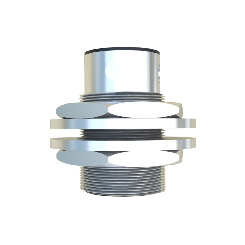
Mechanical factors are frequently overlooked. Vibration can loosen sensor mounting hardware, gradually shifting its position out of alignment with the target. Excessive vibration can also cause internal component failure. Ensure all mounting brackets and hardware are secure. Physical damage from impacts, especially to the sensing face or cable gland, can compromise integrity. Inspect the cable for cuts, pinch points, or insulation damage, particularly at stress points near the connector or entry into the control cabinet. For cylindrical sensors, check that the locking nut is properly tightened to prevent rotation or movement.
Diagnostic tools are essential for efficient troubleshooting. A digital multimeter is the first line of defense. For a 3-wire DC sensor, measure the voltage between the output wire (typically black or blue) and the negative terminal with and without a target present. The voltage should switch cleanly between a high state (near supply voltage for a PNP sourcing sensor) and a low state (near 0V). A sluggish transition or an intermediate voltage often indicates a failing output transistor. An oscilloscope is invaluable for diagnosing electrical noise issues, revealing superimposed spikes or ripple on the supply or signal lines. Some advanced sensors feature diagnostic LEDs that indicate power status and output switching; a constantly lit or unlit output LED when a target is presented/removed is a clear fault indicator.
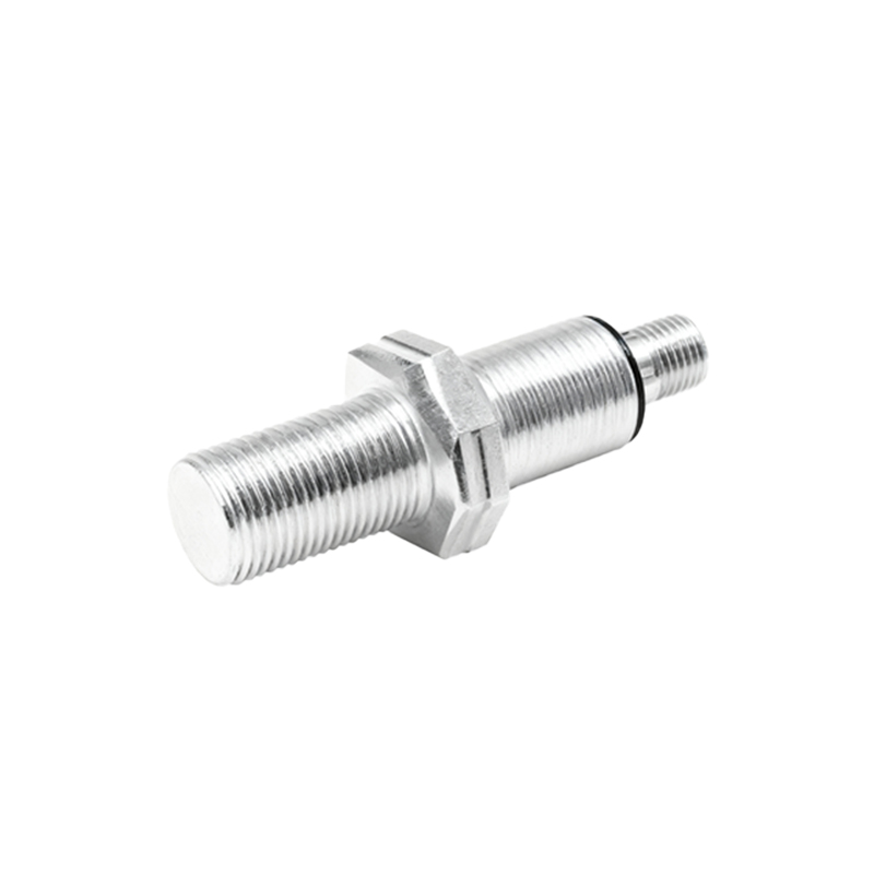
Preventive maintenance is key to minimizing downtime. Establish a regular schedule for inspecting sensor alignment, cleaning faces, checking cable integrity, and verifying electrical connections. Consider the operating environment: in harsh conditions, select sensors with appropriate IP (Ingress Protection) and NEMA ratings for dust and moisture resistance. For high-vibration areas, choose models with robust construction and secure mounting options. Keeping a log of sensor failures, including model, location, and diagnosed cause, can reveal patterns and inform future design or procurement decisions.
When a sensor is confirmed faulty, replacement with an identical model is often the fastest solution. However, this is an opportunity to re-evaluate the application. Was the sensor under-specified? Would a different sensing technology (e.g., ultrasonic, photoelectric) be more robust for the specific target and environment? Upgrading to a unit with a wider operating voltage range, higher environmental ratings, or built-in diagnostics like IO-Link can improve long-term reliability and provide richer diagnostic data directly to the PLC.
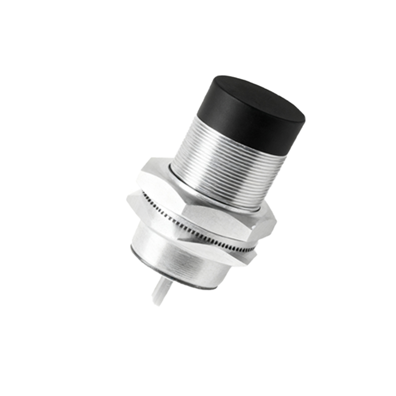
In conclusion, systematic troubleshooting of proximity sensor faults involves a methodical process of elimination: inspect the environment and target, verify mechanical installation, check electrical parameters, and utilize appropriate diagnostic tools. Understanding the common failure modes enables engineers and technicians to quickly restore operation and implement design changes to prevent recurrence, thereby ensuring optimal performance of automated systems.