In industrial automation and machinery design, M8 proximity sensors are widely utilized for their compact size, reliability, and ease of installation. A critical aspect of integrating these sensors is understanding their mounting hole specifications and layouts, which ensure proper alignment, stability, and functionality. This article details the standard hole configurations for M8 proximity sensors, covering threaded and non-threaded variants, along with practical considerations for implementation.
The most common mounting style for M8 proximity sensors is the threaded barrel design. Typically, these sensors feature an M8×1.0 metric thread along the body, allowing them to be screwed directly into a pre-tapped hole. The standard hole for this type is a through-hole or blind hole with an M8×1.0 internal thread, matching the sensor's external threading. The hole depth should accommodate the sensor's threaded length, usually ranging from 15mm to 40mm depending on the model. It is essential to ensure the hole is perpendicular to the mounting surface to avoid misalignment, which could affect sensing accuracy. For through-holes, a lock nut is often used on the opposite side to secure the sensor and prevent loosening due to vibration.
In addition to threaded mounts, some M8 proximity sensors are designed for bracket or flange mounting. These models may include mounting holes on a separate flange or housing. A typical flange might have two or four M3 or M4 threaded holes spaced symmetrically around the sensor body. For instance, a common layout involves two M3 holes with a center-to-center distance of 20mm, allowing the sensor to be fastened to a machine frame or bracket using screws. The flange holes are usually positioned to keep the sensor's sensing face flush with the target area, minimizing dead zones. When designing mounting plates, engineers must account for the flange dimensions and hole patterns to avoid interference with adjacent components.
Another key consideration is the hole for cable or connector clearance. M8 proximity sensors often come with an integrated cable or a standard M8 connector (typically 3-pin or 4-pin). For rear-connected models, a clearance hole must be provided behind the mounting location to allow the cable or connector to pass through without strain. This hole diameter is generally around 10mm to 12mm, but it can vary based on the connector type. Ensuring adequate space prevents cable damage and maintains IP ratings for dust and water resistance. In environments with high movement or vibration, strain relief mechanisms may be incorporated into the hole design.
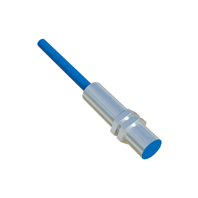
Material and environmental factors also influence hole specifications. In corrosive or washdown environments, stainless steel M8 sensors are preferred, and mounting holes should be made from compatible materials to prevent galvanic corrosion. Hole tolerances are crucial; too loose a fit can lead to sensor wobble, while too tight a fit may cause threading issues. For non-threaded press-fit applications, holes are usually precision-drilled to a diameter of 8.0mm to 8.1mm with a smooth finish. Engineers should refer to manufacturer datasheets for exact dimensions, as variations exist between brands like Omron, Schneider, or Sick.
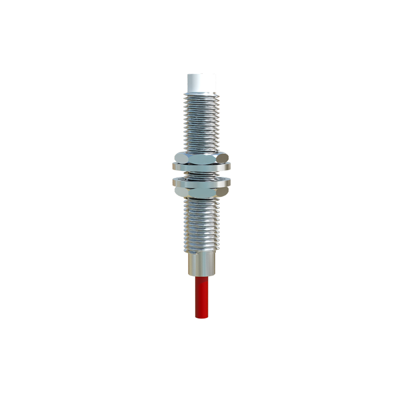
Installation best practices include using a torque wrench to tighten threaded sensors to the recommended value, typically 5-10 Nm, to avoid over-tightening that could damage the housing. For flange mounts, thread-locking adhesives may be applied to screws in high-vibration settings. Additionally, alignment tools or jigs can ensure holes are drilled accurately during assembly. Proper hole placement relative to the target object is vital; for inductive sensors, the sensing distance may be affected by nearby metal, so holes should be positioned to maintain the specified sensing range.
In summary, M8 proximity sensor mounting holes vary by type—threaded, flanged, or press-fit—each requiring specific dimensions and layouts. Adhering to standardized specifications ensures reliable operation, longevity, and safety in automated systems. Always consult technical drawings and guidelines from sensor manufacturers to tailor hole designs to your application's needs.