Proximity sensors are widely used in industrial automation, robotics, and safety systems to detect the presence or absence of objects without physical contact. These sensors typically output a voltage signal that corresponds to the detection state, and accurately measuring this output voltage is crucial for ensuring proper system functionality, troubleshooting, and calibration. This article provides a step-by-step guide on how to measure the output voltage of proximity sensors, covering essential tools, procedures, and best practices for engineers and technicians in the electrical and automation fields.
First, it is important to understand the types of proximity sensors and their output configurations. Common proximity sensors include inductive, capacitive, and photoelectric sensors, each with specific operating principles. Most proximity sensors provide either an analog voltage output (e.g., 0-10 V DC) or a digital voltage output (e.g., 0 V for "off" and 10-30 V DC for "on"). Analog outputs vary continuously based on the distance to the target, while digital outputs switch between two voltage levels. Before measurement, refer to the sensor's datasheet to identify the expected output range, polarity, and load conditions. This information ensures accurate interpretation of the readings and prevents damage to the sensor or measuring equipment.
To measure the output voltage, you will need a digital multimeter (DMM) or an oscilloscope, depending on the application. For steady-state digital outputs, a DMM set to DC voltage mode is sufficient. For analog outputs or dynamic signals, an oscilloscope is recommended to observe voltage variations over time. Ensure that the measuring instrument has appropriate input impedance (typically 1 MΩ or higher for DMMs) to avoid loading the sensor output, which could distort the voltage reading. Additionally, prepare necessary accessories such as test leads, probes, and possibly a power supply if the sensor requires external excitation.
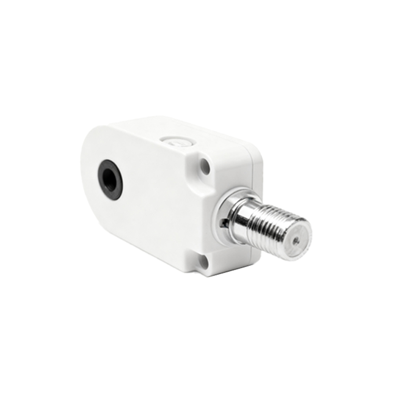
Begin by powering the proximity sensor according to its specifications. Most sensors operate on DC voltages ranging from 10 to 30 V DC. Connect the sensor's power supply wires to a stable DC source, and verify that the sensor is correctly wired—typically, brown wire for positive (+), blue wire for negative (-), and black wire for the output signal. Once powered, the sensor may have an indicator LED that lights up when active, providing a visual cue of its status.
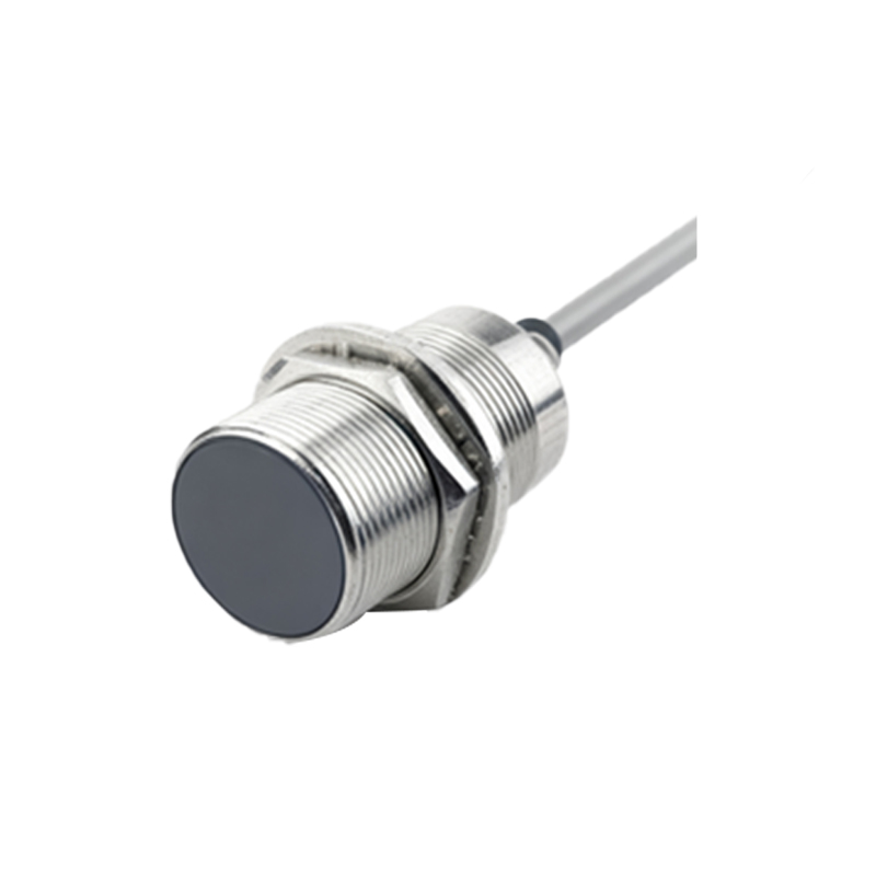
Next, connect the measuring instrument to the sensor's output terminal. For digital outputs, place the DMM's red probe on the output wire (black) and the black probe on the ground or negative terminal (blue). Set the DMM to measure DC voltage within the expected range (e.g., 0-30 V DC). The reading should show either a low voltage (close to 0 V) when no target is detected or a high voltage (e.g., 10-30 V) when a target is within range. To test this, introduce a valid target material (e.g., metal for inductive sensors) at the specified sensing distance and observe the voltage change. For analog outputs, the voltage will vary proportionally with distance; use the DMM to record minimum and maximum values, ensuring they match the datasheet specifications.
If using an oscilloscope, connect its probe to the output terminal and ground, then set the timebase and voltage scale appropriately. Trigger the scope to capture the output signal when the target moves in and out of range. This allows you to analyze rise/fall times, noise, and stability, which are critical for high-speed applications. Note any anomalies such as voltage spikes or droops that could indicate wiring issues, electromagnetic interference, or sensor malfunction.
When measuring, consider environmental factors that might affect accuracy. Electrical noise from nearby motors or switching devices can induce fluctuations in the output voltage. Use shielded cables and proper grounding techniques to minimize interference. Additionally, ensure that the load connected to the sensor output (e.g., a PLC input) does not exceed the sensor's rated current capacity, as overloading can cause voltage drops. If necessary, measure the voltage under load to verify real-world performance.
For troubleshooting, compare the measured voltage with the sensor's datasheet values. If the output is outside the specified range, check the power supply voltage, wiring connections, and sensor alignment. Dirty or damaged sensing faces can also lead to erratic outputs. Calibration may be required for analog sensors; some models include potentiometers for adjusting the output span or threshold. Follow the manufacturer's instructions to fine-tune the sensor using the measured voltage as feedback.
In summary, measuring the output voltage of proximity sensors involves selecting the right tools, understanding sensor specifications, and following systematic procedures. Regular voltage checks help maintain system reliability and prevent downtime in industrial settings. By mastering these techniques, engineers can ensure optimal sensor performance and integrate proximity detection seamlessly into automated processes.