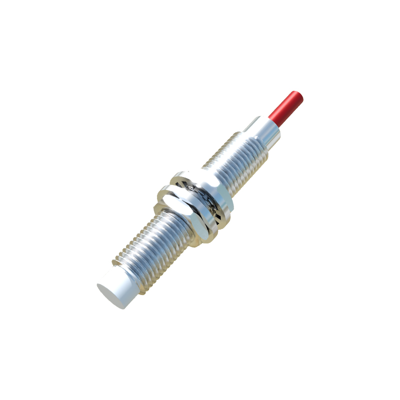
In the realm of industrial automation and control systems, proximity sensors are indispensable components for non-contact object detection. Among the various configurations available, the PNP normally open (NO) 3-wire sensor stands out for its widespread application and reliable performance. This article delves into the operational principles, wiring methodology, and practical considerations for this specific sensor type, providing a comprehensive guide for engineers and technicians.
Fundamentally, a proximity sensor detects the presence or absence of a metallic object (typically ferrous or non-ferrous metals, depending on the technology—inductive, capacitive, or magnetic) without physical contact. The PNP designation refers to the transistor type used in the sensor's output switching circuit. A PNP sensor switches the positive voltage supply to the load. In a "normally open" configuration, the output circuit is open (non-conducting) when no target is present. When a target enters the sensor's sensing range, the output circuit closes, allowing current to flow from the sensor's output wire to the load, thereby signaling detection.
The 3-wire design is the most common for DC-powered sensors, providing a balance of functionality and simplicity. The three wires are universally color-coded for ease of installation: brown for the positive supply voltage (+V, typically 10-30V DC), blue for the common negative or 0V, and black for the output signal. It is crucial to note that the black wire is the switched positive output in a PNP sensor. The load (e.g., a PLC input module, relay coil, or indicator lamp) is connected between this black output wire and the blue common negative wire. When activated, the sensor internally connects the brown (supply) to the black (output), providing a positive voltage signal to the load relative to common negative.
Understanding the switching state is paramount. For a PNP Normally Open sensor: In the idle state (no target detected), the output transistor is off. The voltage measured between the black and blue wires is essentially 0V, as the circuit is open. No current flows to the load. In the active state (target within sensing range), the output transistor turns on. The voltage between the black output and blue common rises to near the supply voltage (e.g., 24V), sourcing current to the load. This "high" signal indicates detection.
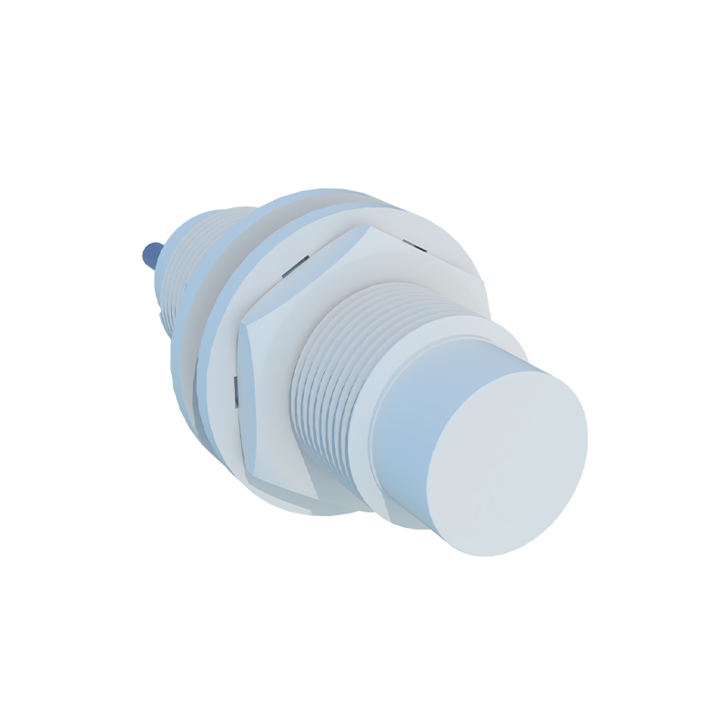
The advantages of using a PNP NO 3-wire sensor are significant. Their compatibility with many programmable logic controller (PLC) sinking input modules is a primary benefit. Since the PNP sensor sources current, it pairs naturally with a PLC input that is configured to receive current (sink). This setup is standard in many European and global designs. The normally open logic is intuitive for control applications where an action should occur only upon detection, such as starting a conveyor motor when a part is present or counting objects as they pass. The 3-wire design provides a dedicated output line, allowing for clear signal monitoring and diagnostics compared to 2-wire versions.
Proper installation and wiring are critical for reliable operation. Always consult the manufacturer's datasheet for specific voltage ratings, sensing distances, and environmental specifications (IP rating). Ensure a stable, clean DC power supply. Connect the brown wire to +V DC, the blue wire to 0V DC, and the black wire to the load. The load's other terminal connects to 0V DC (blue). Incorrect wiring, such as confusing PNP with NPN (which switches the negative side), can lead to malfunction or damage. Use shielded cables in electrically noisy environments and ground the shield properly at one end. Maintain the specified mounting conditions, as surrounding metal (flush vs. non-flush mounting) can affect the nominal sensing distance.
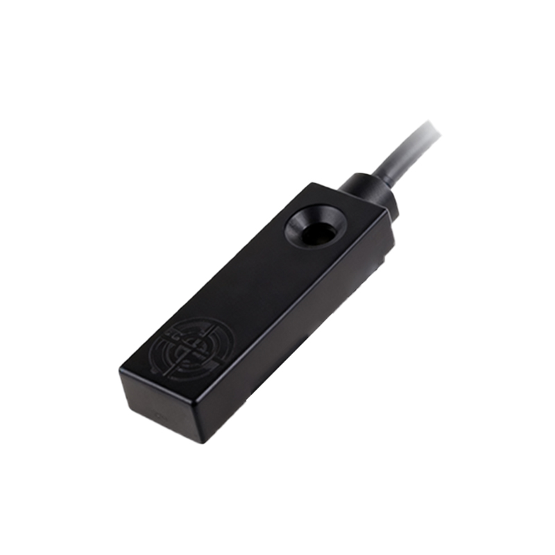
Troubleshooting typically involves a systematic approach. Use a multimeter to verify power between brown and blue wires. With no target present, the voltage between black (output) and blue should be low (near 0V). When a target is introduced, this voltage should rise to the supply level. If the sensor does not switch, check for correct target material and size, ensure it is within the sensing range, and verify there is no buildup of debris on the sensing face. Also, confirm the load is not faulty or drawing excessive current beyond the sensor's rated capacity.
In summary, the PNP normally open 3-wire proximity sensor is a robust, industry-standard solution for automated detection tasks. Its design offers a straightforward interface with control systems, providing a clear, sourced positive signal upon target detection. By adhering to correct wiring practices and understanding its operational logic, engineers can ensure these sensors deliver precise, reliable performance in diverse industrial environments, from packaging and material handling to automotive assembly and beyond. Their role in enabling efficient, error-free automation processes continues to be foundational.