Proximity sensors are indispensable components in modern industrial automation, providing non-contact detection of metallic or non-metallic objects. Correct wiring is fundamental to their reliable operation, safety, and longevity. This guide details the standard procedures for connecting common types of proximity sensors, focusing on practical considerations for engineers and technicians.
Understanding Proximity Sensor Types and Outputs
Before wiring, identify the sensor type and its output configuration. The two primary categories are Inductive (detects metals) and Capacitive (detects metals, plastics, liquids, etc.). Each type typically comes in three main DC output configurations:
1. NPN (Sinking Output): The output switch connects the load to common negative (0V). The load is connected between the sensor's output wire and the positive supply (+V). Common in European and Asian designs.
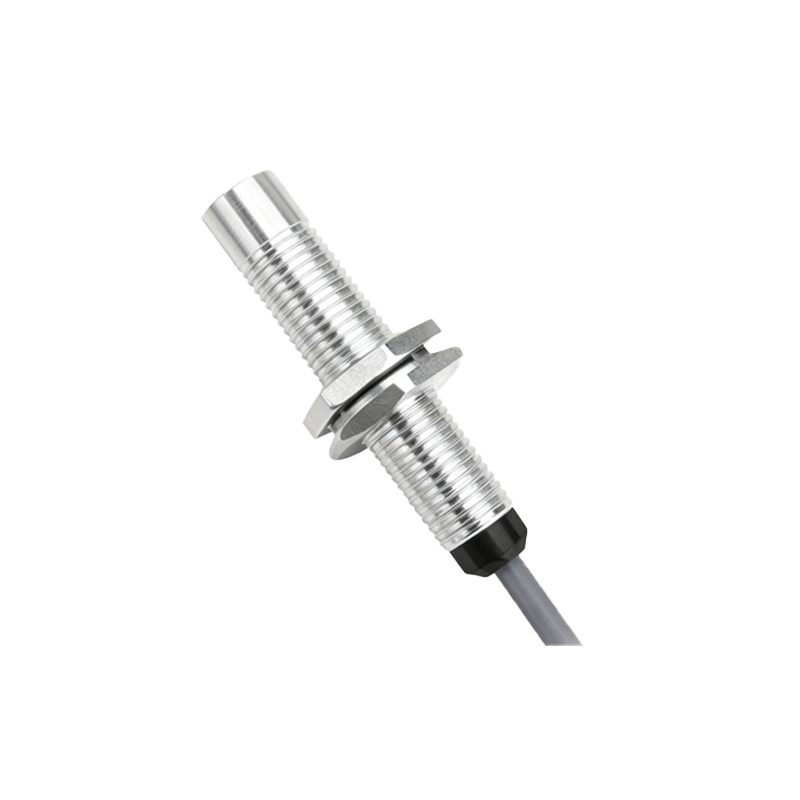
2. PNP (Sourcing Output): The output switch connects the load to common positive (+V). The load is connected between the sensor's output wire and the negative supply (0V). Common in North American designs.
3. NAMUR (Intrinsically Safe): A two-wire sensor with a low-current output used in hazardous areas, requiring an isolated barrier or amplifier interface.
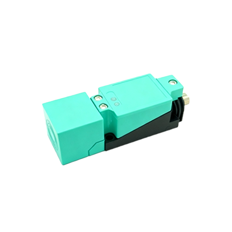
Always consult the manufacturer's datasheet for the specific model's electrical characteristics, including operating voltage range (commonly 10-30V DC), output current, and wiring diagram.
Standard Three-Wire and Four-Wire DC Sensor Wiring
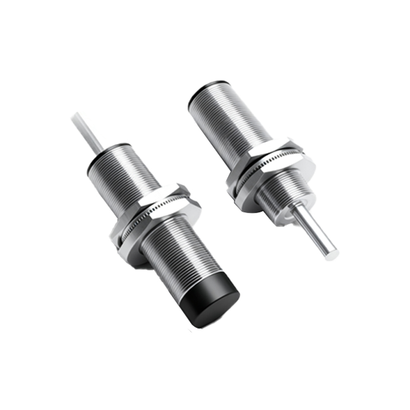
Most industrial DC proximity sensors use a three-wire connection. The wires are typically color-coded: Brown for positive supply (+V), Blue for common negative (0V), and Black (sometimes White or Gray) for the output signal. A fourth wire, often White or Gray, may be present for a complementary output (e.g., normally closed) or diagnostic function.
Step-by-Step Wiring Procedure:
1. Power Disconnection & Safety: Ensure the main control circuit power is LOCKED OUT and TAGGED OUT (LOTO). Verify voltage absence with a multimeter. This is the most critical safety step.
2. Identify Wires & Terminals: Refer to the sensor's label or datasheet. For a standard 3-wire sensor:
Brown wire: Connect to DC positive (+V, e.g., +24V).
Blue wire: Connect to DC common/negative (0V).
Black wire: Connect to the input of your controller (PLC, relay, etc.).
3. Prepare Connections: Use appropriate wire gauges as per current rating. Strip wire ends properly and use crimp ferrules for screw terminals to ensure a secure, reliable connection and prevent stray wires.
4. Connect Power Supply Wires: First, connect the Brown (+V) and Blue (0V) wires to the corresponding terminals of your DC power supply. Ensure polarity is correct. Reverse polarity can permanently damage the sensor.
5. Connect the Output Load: Connect the sensor's Black output wire to the input module of your PLC, a relay coil, or another load device.
For a PNP sensor: The load must be connected between the Black wire and 0V. The PLC input receives the positive signal.
For an NPN sensor: The load must be connected between the Black wire and +V. The PLC input receives the switching to 0V (sinking input).
6. Shielding & Conduit (If Required): In electrically noisy environments, use a shielded cable. Connect the cable shield to a functional earth ground at the control panel end only. Do not connect the shield at both ends to avoid ground loops.
7. Power-Up and Test: Restore power. Use the sensor's LED indicator (if equipped) to verify operation. Bring a target object within the sensing range. The LED should illuminate (or change state). Simultaneously, monitor the input indicator on your PLC or use a multimeter to confirm the output signal switches correctly.
Two-Wire AC/DC Sensor Wiring
Two-wire sensors are wired in series with the load and the power supply, similar to a mechanical switch. They are simpler but have a residual voltage drop ("leakage current") when off, which must be compatible with the connected load's minimum operating current. Ensure the sensor's voltage rating (e.g., 20-250V AC/DC) matches your supply.
Critical Best Practices and Troubleshooting Tips
Mounting: Ensure proper metal-free mounting distance for inductive sensors to avoid reduced sensing range.
Sink/Source Compatibility: Mismatching an NPN sensor with a PLC card configured for PNP (s