Proximity sensors are indispensable components in modern industrial automation, serving as the critical "eyes" of machinery by detecting the presence or absence of objects without physical contact. Their reliability directly impacts production line efficiency, safety, and product quality. However, like all electronic components, they have a finite lifespan and may require replacement due to failure, obsolescence, or system upgrades. This guide provides a systematic, industry-standard approach to replacing proximity sensors, ensuring minimal downtime and optimal performance post-installation.
The replacement process begins not with physical removal, but with meticulous preparation and diagnosis. Before any action is taken, it is paramount to isolate the equipment from all power sources—electrical, pneumatic, and hydraulic—following established Lockout-Tagout (LOTO) procedures. Safety is non-negotiable. Once the system is safely de-energized, the initial step is to confirm sensor failure. Use a multimeter to check the output signal against the sensor's datasheet specifications under the expected detection conditions. Often, issues perceived as sensor failure can stem from wiring faults, power supply problems, or target material/position changes. Verify the sensor's model number, sensing type (inductive, capacitive, photoelectric), sensing distance, output configuration (PNP/NPN, NO/NC), and electrical ratings (voltage, current). Document these parameters and the existing wiring scheme with photographs or diagrams.
Selecting the correct replacement sensor is crucial. While an exact OEM match is ideal, it is not always available. In such cases, cross-referencing based on technical specifications is necessary. Key parameters for selection include:
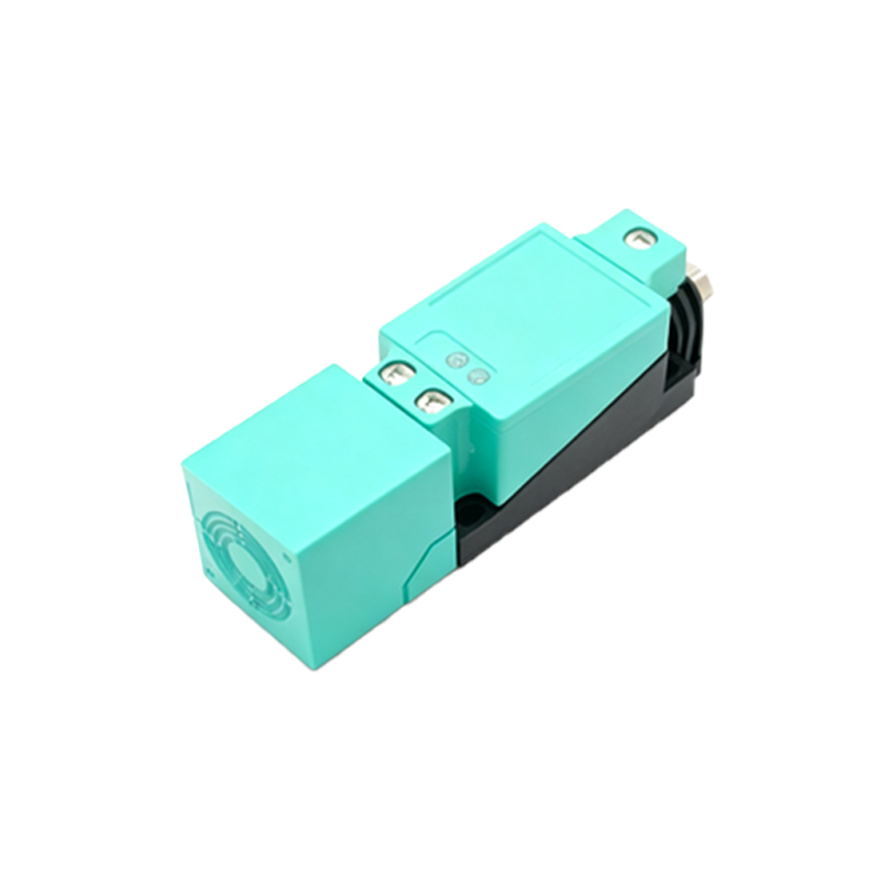
Sensing Principle: Inductive sensors detect metals; capacitive sensors detect a wider range of materials including liquids and plastics; photoelectric sensors use light beams.
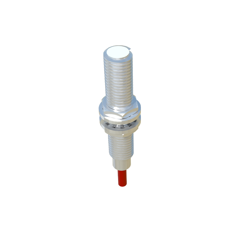
Form Factor and Mounting: Dimensions, thread size (e.g., M8, M12, M18, M30), and mounting style (flush, non-flush, cylindrical, rectangular) must match the existing fixture.
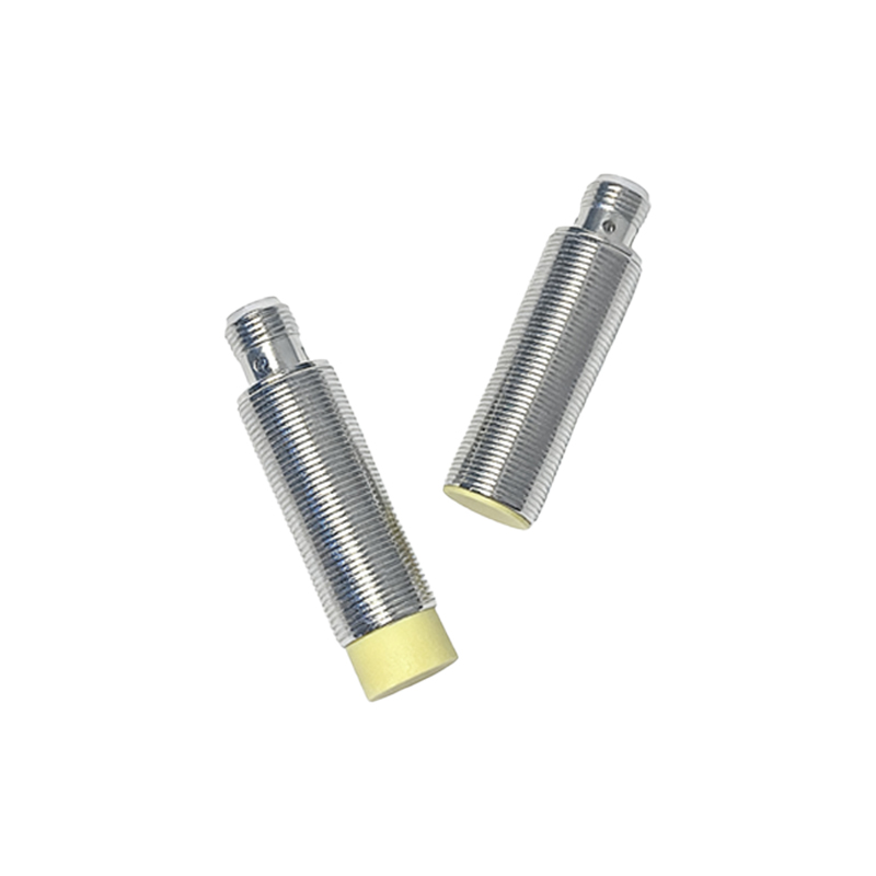
Electrical Characteristics: Operating voltage range (e.g., 10-30V DC), output type (e.g., PNP normally open), and current rating must be compatible with the PLC or control system input card.
Performance Specifications: Rated sensing distance, repeat accuracy, response frequency, and environmental ratings (IP67, IP69K for washdown, temperature range) must meet or exceed the original requirements.
After procuring the correct replacement, proceed with the physical installation. Carefully disconnect the electrical connector or wiring. For threaded barrel sensors, use the appropriate spanner on the hex flats to avoid damaging the housing. Clean the mounting area to remove debris, metal shavings, or coolant residue. Install the new sensor, ensuring it is seated correctly and tightened to the specified torque to prevent loosening from vibration. Reconnect the wiring, paying strict attention to polarity: brown wire to positive (+V), blue wire to negative (0V), and black (or white) wire as the signal output to the controller. Incorrect wiring is a common cause of immediate failure.
Commissioning and testing are the final, critical phases. Before restoring full power, perform a visual inspection of the installation and wiring. If possible, apply power in a controlled manner. Use the sensor's built-in indicator LED (if present) as a primary diagnostic tool. A steady LED typically indicates power; a blinking or activated LED indicates target detection. Manually introduce the target material to the sensing face at the normal operating distance. Observe the LED and simultaneously measure the output voltage with a multimeter to confirm the switching state. Finally, integrate the sensor into the machine control sequence. Run the machine through several slow, manual cycles to verify the sensor triggers at the correct point in the process. Monitor for several production cycles to ensure consistent operation under normal speeds and loads.
Common pitfalls to avoid include ignoring environmental factors like excessive heat, chemical exposure, or electromagnetic interference from nearby motors or welders, which can degrade sensor performance. Ensure the target material and size are within the sensor's specifications; a smaller or non-ferrous target may require a reduced sensing distance. Always reference the manufacturer's technical datasheet—it is the ultimate authority for installation, wiring, and adjustment procedures. A methodical approach to proximity sensor replacement, emphasizing safety, accurate specification matching, and thorough testing, is a hallmark of professional industrial maintenance, ensuring sustained automation reliability and productivity.