Proximity sensors are indispensable components in modern industrial automation, offering non-contact detection of metallic and non-metallic objects. Proper calibration and debugging are critical to ensure reliable operation, minimize false triggers, and extend sensor lifespan. This guide provides a systematic approach to installing, calibrating, and troubleshooting inductive, capacitive, and magnetic proximity sensors commonly used in manufacturing and machinery.
Before beginning calibration, ensure the sensor is correctly installed. Verify the mounting alignment, ensuring the sensing face is parallel to the target object and free from obstructions. Maintain the recommended sensing distance, typically 50-80% of the sensor’s rated range, to account for environmental variations. For inductive sensors, the target material (e.g., steel, aluminum, copper) affects the effective sensing range—consult the datasheet for reduction factors. Capacitive sensors require adjustment for material density and dielectric constant, while magnetic sensors depend on magnetic field strength.
Power the sensor according to its specifications (e.g., 10-30V DC for most models). Use a stable power supply with adequate current capacity, and ensure proper grounding to reduce electrical noise. Connect the output to a programmable logic controller (PLC) or relay, and verify wiring polarity to prevent damage. For sensors with adjustable parameters (e.g., sensitivity, hysteresis, response time), reset them to factory defaults initially.
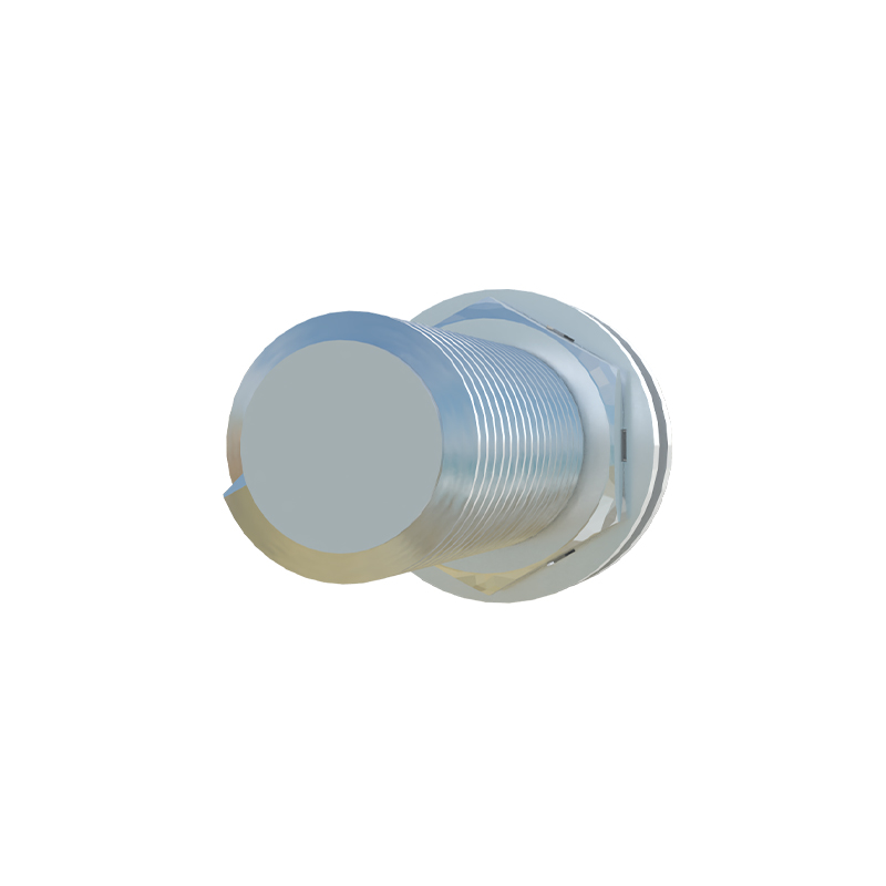
Calibration involves setting the sensing threshold. Place a standard target (specified in the datasheet) within the sensing range. Adjust the sensitivity potentiometer or teach-in button until the output activates consistently. For analog sensors, map the output signal (e.g., 4-20mA, 0-10V) to the desired measurement scale using a calibrator. Perform multiple tests with the target at different positions to ensure repeatability. Record the settings for future reference.
Environmental factors significantly impact performance. Electrical interference from motors or frequency drives can cause erratic behavior. Shield cables, use twisted-pair wiring, and install ferrite cores if necessary. Temperature extremes may drift the sensing range; operate within the rated temperature span. Contaminants like dust, oil, or coolant can affect capacitive sensors—select models with appropriate IP ratings and clean sensing surfaces regularly.
Debugging starts with symptom analysis. Common issues include no output signal, intermittent operation, or premature triggering. Use a multimeter to check voltage at the sensor terminals. If power is correct but no output occurs, test with a known-good target. For false triggers, increase the hysteresis setting or adjust mounting to avoid vibration interference. Check for nearby metal objects or sensors installed too close to each other, which may cause mutual interference.
Advanced diagnostics involve oscilloscope analysis of output waveforms to detect noise or delay issues. For networked sensors using IO-Link or AS-Interface, utilize configuration software to monitor real-time parameters and log events. Update firmware if available to resolve known bugs.
Regular maintenance includes periodic recalibration, especially after mechanical shocks or environmental changes. Keep a log of calibration dates, settings, and performance metrics. Replace sensors showing consistent drift or physical damage.
By following these steps, engineers can optimize proximity sensor performance, reduce downtime, and enhance system reliability. Always prioritize safety: lock out equipment during calibration and adhere to local electrical codes.