In industrial automation and control systems, proximity sensors are widely used for non-contact detection of metallic or non-metallic objects. Among various types, two-wire proximity sensors are popular due to their simplicity and ease of installation. However, wiring multiple two-wire sensors in series can be challenging if not done correctly. This article provides a detailed guide on how to properly connect two-wire proximity sensors in series, ensuring reliable operation and system integrity.
Two-wire proximity sensors function as switches that open or close based on the presence of a target. Unlike three-wire sensors, which have separate power, ground, and signal wires, two-wire sensors combine the power and signal paths into two wires. This design simplifies wiring but requires careful consideration when connecting multiple sensors in series. The primary goal of series wiring is to allow multiple sensors to control a single load, such as a relay or PLC input, by creating a chain where the sensors' output states are logically combined.
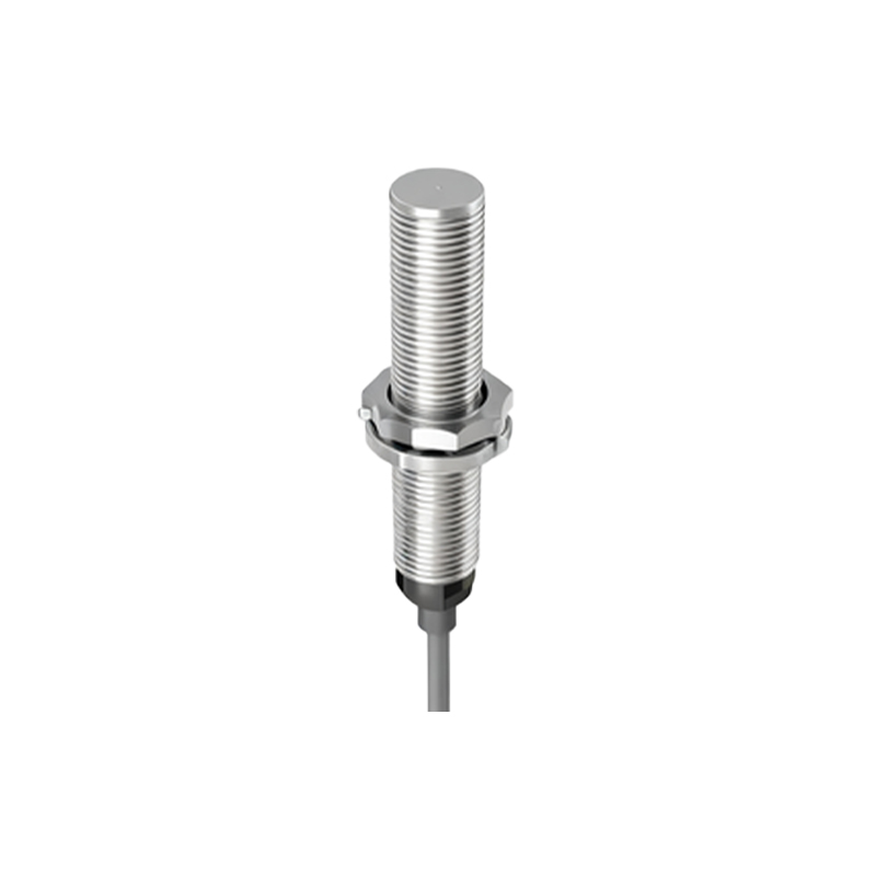
Before starting the wiring process, it is essential to understand the electrical characteristics of the sensors. Two-wire sensors typically operate on DC or AC voltage, with common ratings being 10-30V DC or 20-250V AC. They have a leakage current when in the "off" state, which can affect the overall circuit if multiple sensors are connected. When wired in series, the sensors must be compatible in terms of voltage, current, and switching logic (normally open or normally closed). Using sensors with mismatched specifications can lead to malfunction or damage.

To wire two-wire proximity sensors in series, follow these steps:
1. Power Supply Connection: Connect the positive terminal of the power supply to the first sensor's brown wire (typically for DC) or the live wire (for AC). For AC sensors, polarity is not critical, but consistency is recommended.
2. Series Linking: Connect the blue wire (or black wire, depending on the model) of the first sensor to the brown wire of the second sensor. This creates a series chain where the current flows through both sensors sequentially.
3. Load Connection: Connect the blue wire of the last sensor in the series to one terminal of the load (e.g., a relay coil). The other terminal of the load should be connected to the negative terminal of the power supply (for DC) or the neutral wire (for AC).
4. Grounding: Ensure proper grounding according to safety standards, especially for AC systems, to prevent electrical hazards.
A critical aspect of series wiring is the voltage drop across each sensor. Since the sensors are in series, the total voltage supplied must be sufficient to account for drops in each sensor and the load. Calculate the total voltage requirement by summing the voltage drops of all sensors and the load. For example, if each sensor drops 2V and the load requires 24V, a 30V supply might be necessary to ensure proper operation. Additionally, consider the total leakage current in the "off" state, as it can cause false triggering if it exceeds the load's threshold.
In practice, series wiring is often used for safety circuits or interlocking systems where all sensors must detect a condition for the load to activate. For instance, in a machine guarding application, multiple proximity sensors might be wired in series to ensure all guards are closed before the machine starts. If any sensor detects an open guard, the circuit breaks, de-energizing the load. This configuration enhances safety but requires regular testing to verify each sensor's functionality.
Common pitfalls in series wiring include using sensors with different switching logic, inadequate power supply voltage, and ignoring leakage current effects. To avoid issues, always refer to the manufacturer's datasheet for specifications and wiring diagrams. Testing the circuit with a multimeter before full operation is advisable to check for proper voltage levels and continuity.
In conclusion, wiring two-wire proximity sensors in series is a viable method for creating logical AND conditions in control systems. By following proper steps and considering electrical parameters, engineers can achieve reliable and safe sensor networks. This approach is cost-effective and efficient for applications requiring multiple detection points, contributing to optimized industrial automation processes.