Proximity sensors are essential components in modern industrial automation, providing non-contact detection of metallic objects. Among the various models available, the E2B series four-wire proximity sensors are widely used due to their reliability and straightforward integration. This article offers a detailed, practical guide to wiring the E2B four-wire sensor, covering principles, steps, and best practices for optimal performance.
The E2B four-wire proximity sensor typically includes two wires for power supply and two for output signals. Unlike two-wire sensors that combine power and signal lines, four-wire designs separate these functions, enhancing stability and reducing interference. Common configurations include NPN or PNP output types, with sourcing (PNP) and sinking (NPN) options to match different control systems. Before wiring, identify the sensor's specifications from its datasheet or labeling: usually, brown wire for positive DC voltage (e.g., +24V), blue wire for negative or ground (0V), black wire for output signal, and white wire for a complementary output or function (such as NO/NC switching). Some models may use alternative color codes, so always verify with manufacturer documentation.
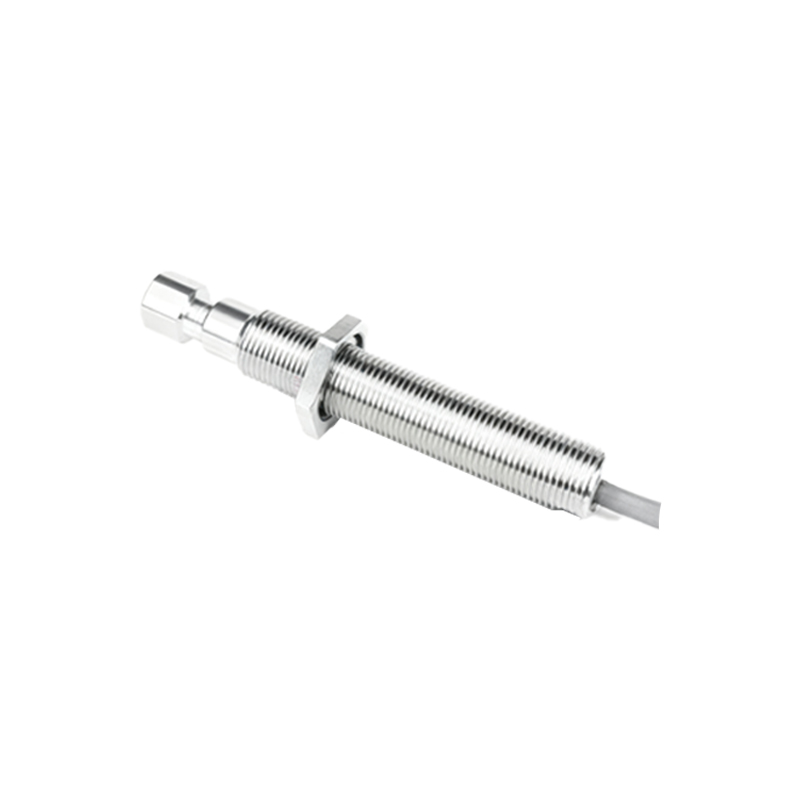
To wire the E2B sensor, start by ensuring a safe power-off state to prevent electrical hazards. Connect the brown wire to the positive terminal of a DC power supply, typically ranging from 10-30V DC, and the blue wire to the negative terminal. This powers the sensor's internal circuitry. Next, link the output wires: for a PNP sensor, the black wire provides a positive signal when an object is detected, so connect it to the input of a PLC, relay, or controller that accepts sourcing inputs. The white wire, if present, can be used for an alternate output mode—consult the manual for specific functions like normally open (NO) or normally closed (NC) operation. For NPN sensors, the black wire outputs a negative signal, requiring connection to a sinking input device. Always use shielded cables in noisy environments, grounding the shield at one end to minimize electromagnetic interference.
Testing is crucial after wiring. Apply power and observe the sensor's indicator LED; it should light up when powered and change state upon detecting a metal target. Use a multimeter to check voltage levels: between brown and blue wires, ensure it matches the supply (e.g., 24V), and between black and blue wires, verify the output switches appropriately (e.g., from 0V to 24V for PNP). Common issues include incorrect polarity, loose connections, or mismatched output types—double-check wiring against diagrams. For longevity, install the sensor away from high-vibration areas, maintain clean sensing surfaces, and adhere to environmental ratings (e.g., IP67 for dust and water resistance).
In summary, proper wiring of the E2B four-wire proximity sensor involves careful attention to wire colors, output types, and system compatibility. By following these guidelines, engineers can ensure reliable operation in applications like conveyor systems, machine safety, and robotic arms, enhancing overall automation efficiency. Regular maintenance and adherence to standards further support sustained performance in industrial settings.