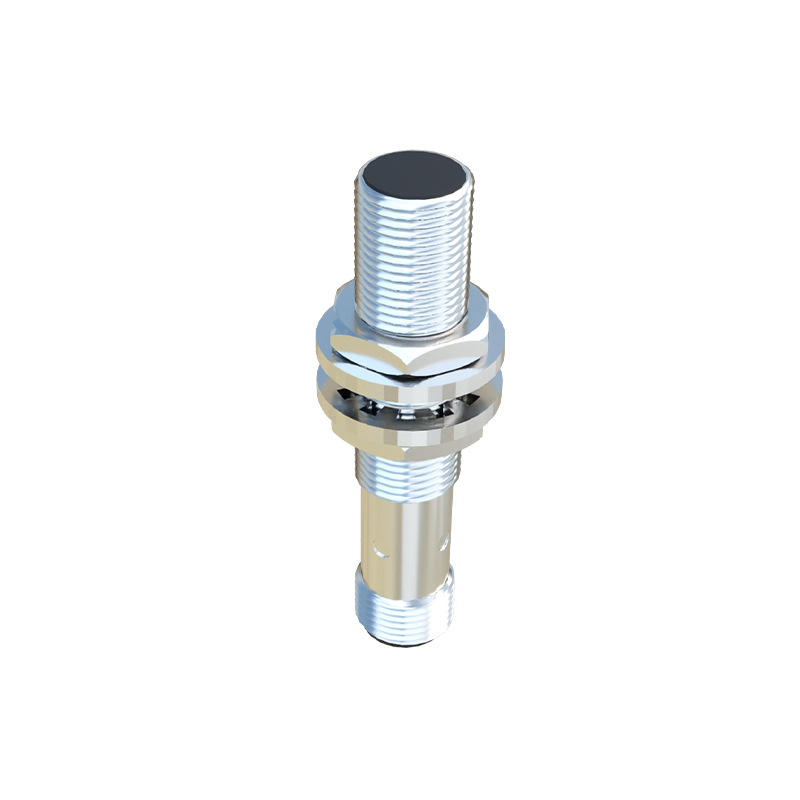
Proximity sensors are essential components in modern industrial automation, providing non-contact detection of objects within a defined range. As an experienced electrical engineer, I aim to demystify the circuit diagrams behind these devices, focusing on inductive and capacitive types commonly used in machinery and safety systems.
A typical inductive proximity sensor circuit consists of an oscillator, a demodulator, a trigger, and an output stage. The core is an LC oscillator where a coil generates a high-frequency electromagnetic field. When a metallic object enters this field, eddy currents are induced, causing a change in oscillation amplitude. This change is detected by the demodulator, which converts it into a DC signal. The trigger circuit then processes this signal to activate the output stage—usually a transistor (NPN or PNP) that switches a load. The circuit is powered by DC (10-30V) or AC, with protection components like diodes for reverse polarity and capacitors for noise filtering. For instance, a 3-wire DC sensor diagram shows V+, V-, and output lines, often including a LED indicator in parallel with the output.
Capacitive proximity sensors, suitable for non-metallic objects, use a similar structure but with a different sensing principle. Their circuit includes an RC oscillator where the capacitance changes when an object alters the dielectric field. The diagram highlights a sensing electrode connected to the oscillator, followed by a comparator that thresholds the signal. These circuits require careful shielding in the layout to prevent false triggers from environmental interference.
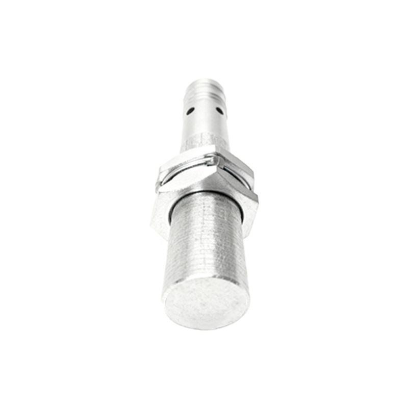
In practice, reading these diagrams involves identifying key symbols: coils for inductive elements, capacitors for capacitive plates, and ICs like 555 timers or op-amps for signal processing. A standard wiring diagram for a 4-wire sensor (two for power, two for output) might include a relay or PLC interface. Engineers must consider factors like sensing distance (e.g., 5mm for M12 sensors), response time (microseconds), and output types (NO/NC). For example, a common industrial circuit integrates a sensor with a microcontroller, using optocouplers for isolation to protect against voltage spikes.
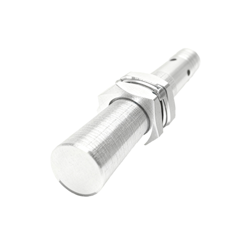
Design tips include adding varistors for surge protection and ensuring proper grounding to reduce EMI. In complex setups, such as conveyor systems, multiple sensors are daisy-chained with interlocking circuits, where diagrams show series/parallel connections for fail-safe operation. Always refer to datasheets for specific pinouts and voltage ratings. By mastering these circuit diagrams, engineers can optimize sensor performance, enhance system reliability, and troubleshoot issues like false detections or output failures efficiently.