Proximity sensors are indispensable components in modern industrial automation, offering non-contact detection of metallic or non-metallic objects. Understanding the original wiring diagram is crucial for ensuring proper installation, optimal performance, and system safety. This guide provides a comprehensive overview of standard proximity sensor wiring configurations, terminal designations, and practical connection examples.
A typical proximity sensor features three or four wires, depending on its type (e.g., NPN, PNP, or AC/DC). The wiring diagram, usually found on the sensor housing or in the manufacturer's datasheet, illustrates the connection points for power supply, load, and ground. For a three-wire DC sensor, the common terminals are: Brown wire (+V or positive supply), Blue wire (0V or negative supply), and Black wire (output signal). In a four-wire sensor, an additional white wire may be used for a second output or diagnostic function.
The core of the wiring diagram is the output configuration. NPN (sinking) sensors switch the negative side of the load to ground, meaning the output wire connects to the load, which is then linked to the positive supply. Conversely, PNP (sourcing) sensors switch the positive side, with the output providing voltage to the load connected to ground. Misinterpreting this can lead to short circuits or non-operation. Always verify the sensor's output type (NPN or PNP) against the PLC or controller input compatibility.
For AC-powered sensors, typically two-wire models, the wiring is simpler: one wire connects to the live AC terminal, and the other connects in series with the load to the neutral. However, attention must be paid to leakage current, which might require a bypass resistor to prevent residual activation of the load.
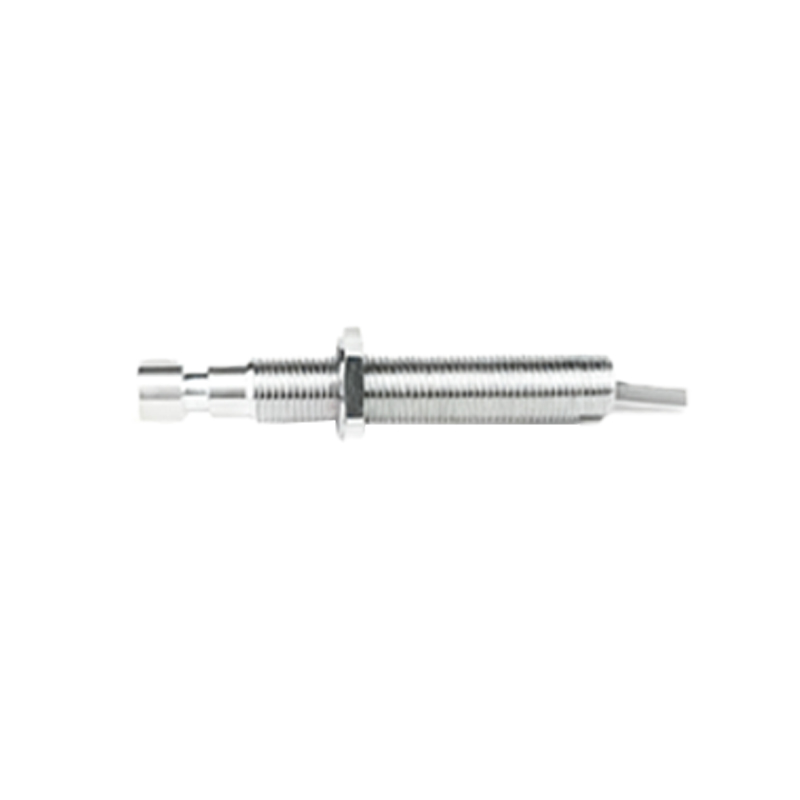
Shielded cables are recommended for long-distance wiring to minimize electromagnetic interference (EMI). The shield should be grounded at only one end, preferably at the control panel, to avoid ground loops. The wiring diagram often indicates shield connection points. Additionally, ensure wire gauges are adequate for the current rating, and use proper conduit or cable trays for mechanical protection.
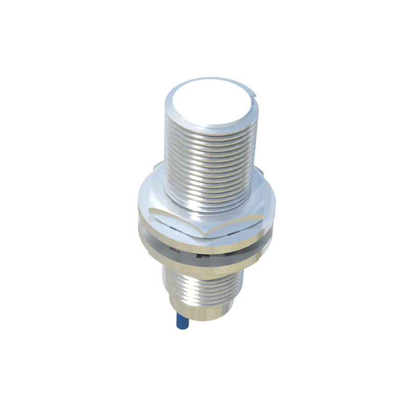
Practical wiring example for a three-wire DC PNP sensor: Connect the brown wire to the +24V DC power supply. Connect the blue wire to the 0V (common) of the power supply. Connect the black (output) wire to one terminal of the load (e.g., a PLC digital input). Connect the other terminal of the load to the 0V. Upon detecting a target, the sensor will source +24V to the load, activating the input.

For an NPN sensor, the black output wire connects to the load, and the load's other side connects to +24V. When active, it sinks current to 0V. Always disconnect power before wiring, and use insulated tools. Double-check connections against the diagram to prevent reverse polarity, which can permanently damage the sensor.
Some advanced sensors feature diagnostic outputs (e.g., short-circuit protection, overload indication) shown in the diagram via additional symbols. Understanding these can aid in troubleshooting. For instance, a steady output LED with no load activation might indicate a wiring error in the load circuit.
In summary, the original wiring diagram is the authoritative reference for correct sensor integration. By following it meticulously, engineers can ensure reliable operation, extend sensor lifespan, and maintain system integrity. Always consult the specific manufacturer's documentation, as terminal colors and functions can vary slightly between brands. Proper wiring not only guarantees functionality but also upholds safety standards in industrial environments.