In industrial automation and control systems, proximity sensors are indispensable components for non-contact detection of objects. A common question among engineers and system integrators is whether the cable length connecting the sensor to the controller, such as a 50-meter run, will lead to significant signal attenuation or performance degradation. The short answer is: it can, but the extent and impact depend on several critical factors. Understanding these factors is key to ensuring reliable system operation.
Firstly, the operating principle of the proximity sensor is fundamental. Inductive sensors detect metallic objects, while capacitive sensors can detect both metallic and non-metallic materials. The sensor generates a high-frequency electromagnetic field or measures capacitance changes. The electrical signal representing the detection state (typically a switching signal like NPN/PNP open-collector or a Namur output, or an analog signal like 4-20mA or 0-10V) must travel through the cable to the evaluation unit or PLC.

Signal attenuation over long cables is primarily caused by three electrical phenomena:
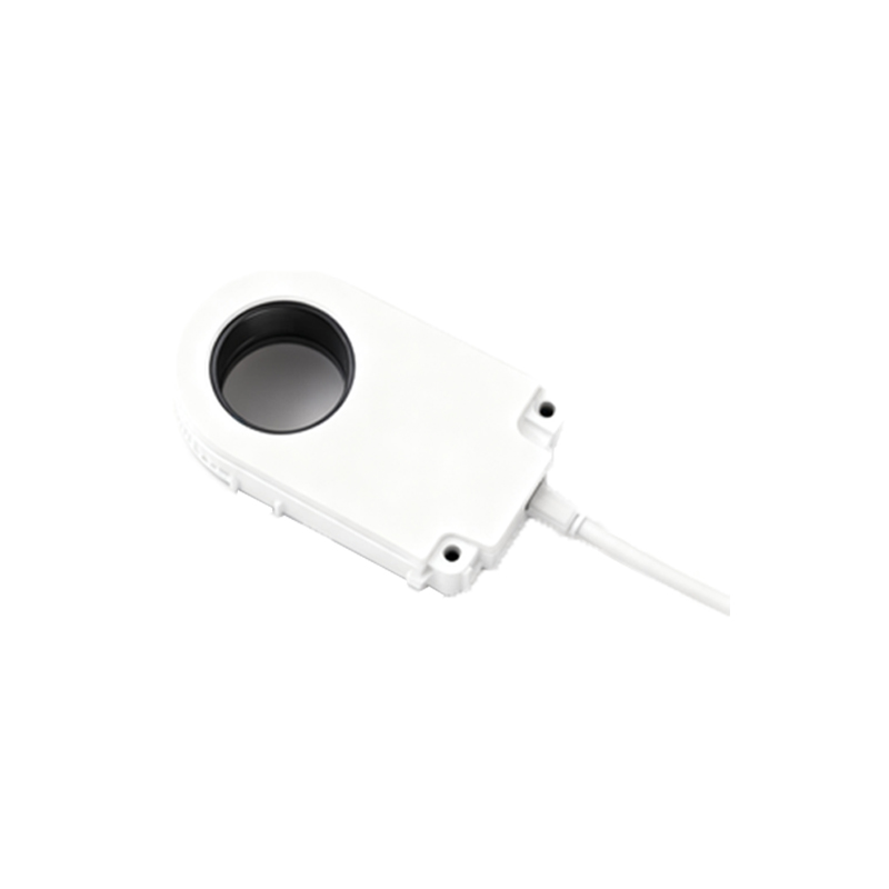
1. DC Resistance (Ohmic Loss): Every cable has inherent resistance per unit length. For a standard unshielded multi-conductor cable (e.g., 2 x 0.75 mm²), the loop resistance for 50 meters can be several ohms. This resistance causes a voltage drop, especially critical for two-wire sensors and analog current loops (4-20mA). While current loops are inherently resistant to voltage drop, ensuring sufficient supply voltage at the sensor end is crucial over 50 meters.
2. Capacitance: The cable itself acts as a distributed capacitor between its conductors and between conductors and shield/ground. Cable capacitance is measured in picofarads per meter (pF/m). Over 50 meters, this capacitance can accumulate to a significant value (e.g., 100-300 pF/m can result in 5-15 nF). For fast-switching digital signals or high-frequency analog signals, high capacitance can slow down the signal rise/fall time, potentially causing missed counts or delayed responses. It can also load the output stage of certain sensor types.
3. Inductance and Impedance Mismatch: While less dominant at lower frequencies, cable inductance and impedance mismatches can cause signal reflections, particularly in high-speed switching applications or with certain communication protocols (e.g., IO-Link over distance).
The sensor's output type dictates its susceptibility:
Analog Current Output (4-20mA): Highly robust against voltage drop over long distances. The signal information is in the current, not the voltage. The primary concern is ensuring the power supply voltage is high enough to overcome the total cable resistance and the minimum operating voltage requirement of the sensor. For 50 meters, this is usually manageable with proper wire gauge.
Analog Voltage Output (0-10V, 0-5V): More susceptible to voltage drop due to cable resistance. The received voltage at the controller will be lower than the sensor's output voltage. Using a larger wire cross-section (e.g., 1.0 mm² or 1.5 mm²) is essential to minimize this drop for 50-meter runs.
Digital Switching Outputs (PNP/NPN): Voltage drop can be an issue, potentially bringing the signal voltage below the PLC's guaranteed "ON" threshold level at the receiving end. Cable capacitance is a major concern as it can smooth out sharp digital edges.
Namur Sensors (Intrinsically Safe): These require a separate amplifier/barrier. The cable length affects the loop parameters and must be considered within the intrinsic safety calculations for the system.
Mitigation Strategies for 50-Meter Installations:
1. Increase Cable Cross-Sectional Area: Using a cable with larger conductors (e.g., 1.0 mm² or 1.5 mm² instead of 0.75 mm²) directly reduces DC resistance, minimizing voltage drop. This is the most straightforward and effective step for voltage-based signals.
2. Choose the Right Output Type: Opt for 4-20mA analog output when long distances and precision are required. For switching applications, ensure the sensor's specified "maximum cable length" (often found in the datasheet, considering capacitance) is not exceeded. Some sensors are explicitly designed for long cable runs.
3. Use Shielded Cables Properly: Always use a braided or foil shield to protect against electromagnetic interference (EMI), which can be misinterpreted as signal attenuation or noise. Ground the shield at only one end (typically the control panel end) to avoid ground loops.
4. Implement Signal Conditioners or Repeaters: For very long runs or problematic environments, installing a