Radar proximity sensors are critical components in modern industrial automation, offering non-contact detection capabilities for various applications. Understanding the correct wiring procedures is essential for ensuring optimal performance and safety. This guide provides a detailed wiring diagram explanation for common radar proximity sensors, focusing on standard configurations and best practices.
Most radar proximity sensors feature a similar wiring structure, typically consisting of power supply connections, output signals, and grounding terminals. The standard wiring diagram includes three main wires: brown (positive), blue (negative), and black (output). The brown wire connects to the positive terminal of the DC power supply, usually ranging from 10V to 30V DC, depending on the sensor model. The blue wire is linked to the negative terminal, completing the power circuit. The black wire serves as the output, transmitting detection signals to controllers like PLCs or relays.
For sensors with additional functionalities, such as analog outputs or IO-Link communication, extra wires may be present. For example, a white wire might represent an analog output (0-10V or 4-20mA), while a gray wire could indicate a second switching output. Always refer to the manufacturer’s datasheet for model-specific details, as color codes can vary. In shielded cable setups, the shield wire must be grounded at one end to prevent electrical interference, ensuring stable signal transmission.
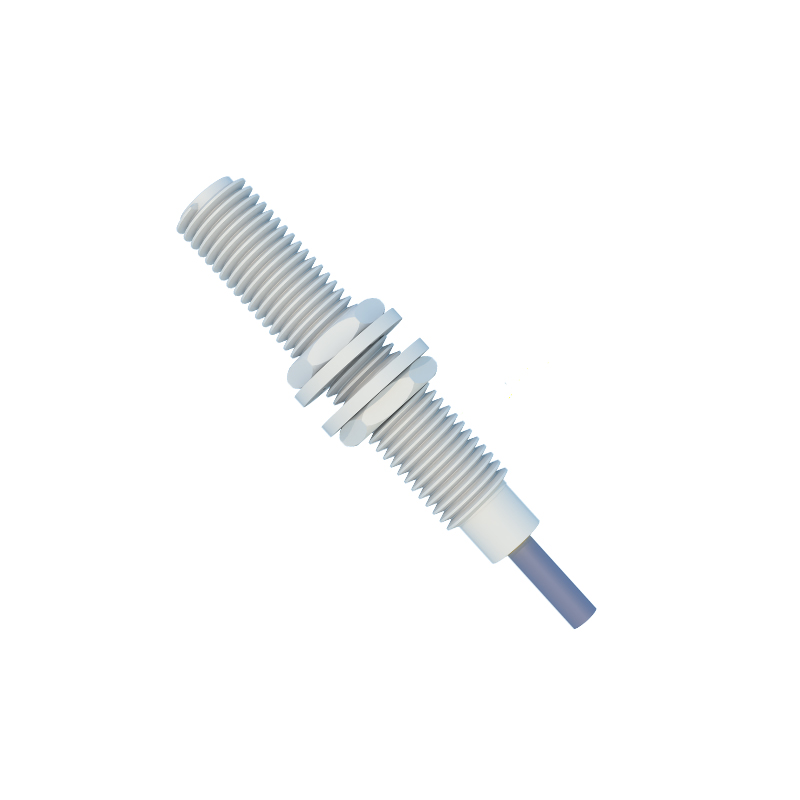
When implementing the wiring, start by disconnecting all power sources to avoid electrical hazards. Strip the wire ends appropriately and secure them to the corresponding terminals using screwdrivers or crimping tools. Maintain proper wire management by avoiding sharp bends and keeping high-voltage cables separate from sensor wires to reduce noise. After connections are made, perform a continuity test with a multimeter to verify correct wiring before powering the system.
Calibration and testing are crucial post-installation steps. Adjust the sensor’s sensitivity and detection range according to the application, such as monitoring conveyor belts or robotic arms. Use indicators like LED lights on the sensor to confirm operation—for instance, a steady light may indicate power, while a blinking light signals object detection. Troubleshoot common issues like false triggers by checking for environmental factors, such as metal reflections or moisture, and ensure the sensor is mounted securely without vibrations.
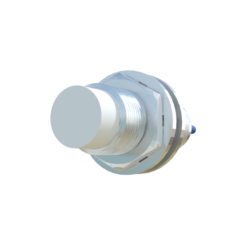
In summary, proper wiring of radar proximity sensors enhances system reliability and longevity. By following standardized diagrams and safety protocols, engineers can minimize downtime and optimize automation processes. Regular maintenance, including cleaning lenses and inspecting connections, further supports consistent performance in industrial settings.