Laser sensors have become indispensable components in modern industrial automation, robotics, and quality control systems. Their precision, speed, and non-contact measurement capabilities make them ideal for a wide range of applications, from object detection and positioning to distance measurement and surface inspection. However, achieving optimal performance from a laser sensor requires meticulous calibration and systematic debugging. This guide outlines professional methods for effectively setting up and troubleshooting laser sensors, ensuring reliable operation in demanding environments.
The initial phase of laser sensor integration involves careful installation and mechanical alignment. The sensor must be mounted securely to minimize vibrations, which can introduce significant measurement noise. The mounting surface should be rigid and stable. Alignment is critical; the laser beam must be perpendicular to the target surface for most reflective and triangulation-based sensors. Even a slight angular deviation can lead to measurement errors, known as cosine error. Use precision mounting fixtures and alignment tools, such as optical levels or alignment lasers, to achieve the correct orientation. Ensure the sensor's operating range, as specified in its datasheet, is appropriate for the application. Placing the target within the sensor's "dead zone" or beyond its maximum range will result in failure.
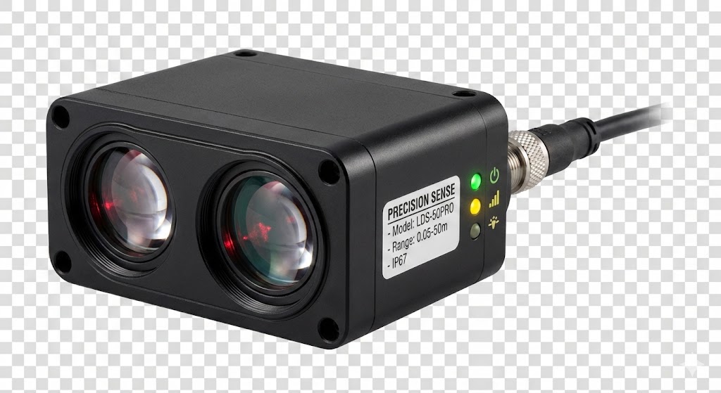
Following physical installation, electrical and interface configuration is the next step. Connect the sensor to a stable power supply that matches its voltage and current requirements, typically 12-24 VDC. Electrical noise from machinery can interfere with sensor signals. Employ shielded cables, proper grounding techniques, and, if necessary, ferrite cores or noise filters on power lines. Most industrial laser sensors offer configurable outputs (e.g., NPN/PNP, analog 0-10V/4-20mA, or digital protocols like IO-Link). Configure the output type and scaling parameters through the sensor's teach-in button, dedicated programming cable, or software interface. For analog sensors, define the scaling so that the minimum and maximum measured distances correspond precisely to the desired output voltage or current range.
Calibration is the process of defining the relationship between the sensor's output signal and the actual physical measurement. Begin with a two-point calibration using known reference targets. Place a target at the minimum measurement distance and trigger the "teach" function to set the lower output value (e.g., 0V or 4mA). Repeat the process with a target at the maximum measurement distance to set the upper output value (e.g., 10V or 20mA). For higher accuracy, a multi-point calibration across the entire range may be performed. Environmental compensation is a crucial part of calibration. Laser sensor readings can be affected by ambient temperature, humidity, and the target's surface properties (color, reflectivity, texture). Many advanced sensors feature automatic background suppression or algorithms to compensate for material color. If not, manual compensation may be required by teaching the sensor on the actual target material under typical operating conditions.
Even with careful setup, issues can arise. A structured debugging approach is essential. Start by verifying the basics: Is the power LED illuminated? Are all connections secure? Use a multimeter to confirm power supply voltage at the sensor terminals. If the sensor has no output, check the wiring of the output circuit against the controller's input requirements (sourcing vs. sinking). For erratic or noisy readings, environmental factors are the primary suspect. Intense ambient light, especially from other lasers or sunlight, can saturate the receiver. Install protective shrouds or filters, and adjust the sensor's exposure time or light intensity setting if available. Dust, smoke, or condensation on the lens will scatter the laser beam, leading to signal loss. Regularly clean the lens with appropriate materials. Vibration can be diagnosed by temporarily isolating the sensor; if readings stabilize, improved damping is needed.
For performance issues like poor repeatability or accuracy drift, systematic testing is required. Use a high-precision positioning stage to move a target and compare the sensor's readings against the stage's known displacement. This reveals linearity errors. Check for hysteresis by approaching the target from different directions. Review the target surface; highly reflective or transparent materials may require a specialized diffuse reflection sensor or a retro-reflective mode. Dark, absorbent surfaces may need a sensor with higher output power. Finally, consult the sensor's diagnostic features. Many modern sensors provide status bits or software tools that indicate signal strength, internal temperature, or error codes, which are invaluable for pinpointing faults.
In conclusion, successful laser sensor deployment hinges on a methodical process: precise mechanical installation, correct electrical integration, thorough calibration for the specific application and environment, and a logical approach to debugging. By adhering to these engineering principles, technicians and engineers can ensure their laser sensing systems deliver the high levels of reliability and accuracy required for advanced industrial automation. Regular maintenance and periodic re-calibration, as part of a preventive maintenance schedule, will sustain long-term performance.