In industrial automation and control systems, proximity switches, particularly inductive types designed for ferrous metal detection, are fundamental components. Their primary function is to detect the presence or absence of a target object without physical contact, triggering a control signal. However, a frequent and disruptive issue encountered on the plant floor is the failure of a ferrous sensor proximity switch to recognize or detect a valid target. This non-detection event can lead to production stoppages, quality defects, and safety concerns. This article delves into the root causes, diagnostic procedures, and corrective actions for this prevalent problem, presented from an engineering perspective.
The principle of operation for an inductive proximity switch is based on generating an electromagnetic field. When a ferrous metal target enters this field, eddy currents are induced within the target, causing a change in the oscillation amplitude within the sensor's internal circuit. This change is detected and converted into a binary output signal. Failure in this chain of events results in non-detection.
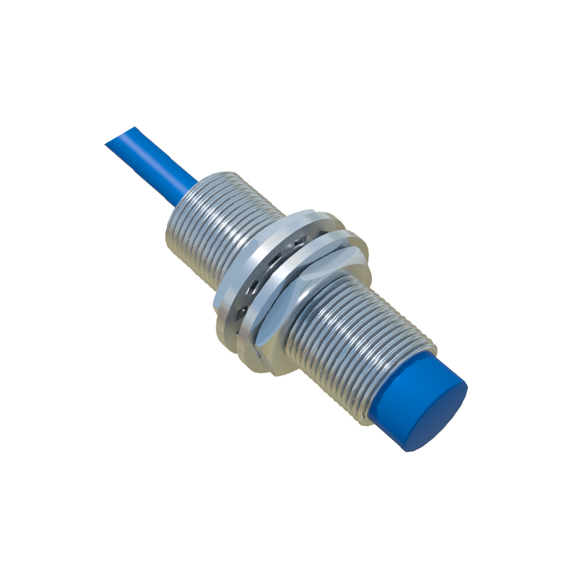
Primary Causes of Non-Detection:
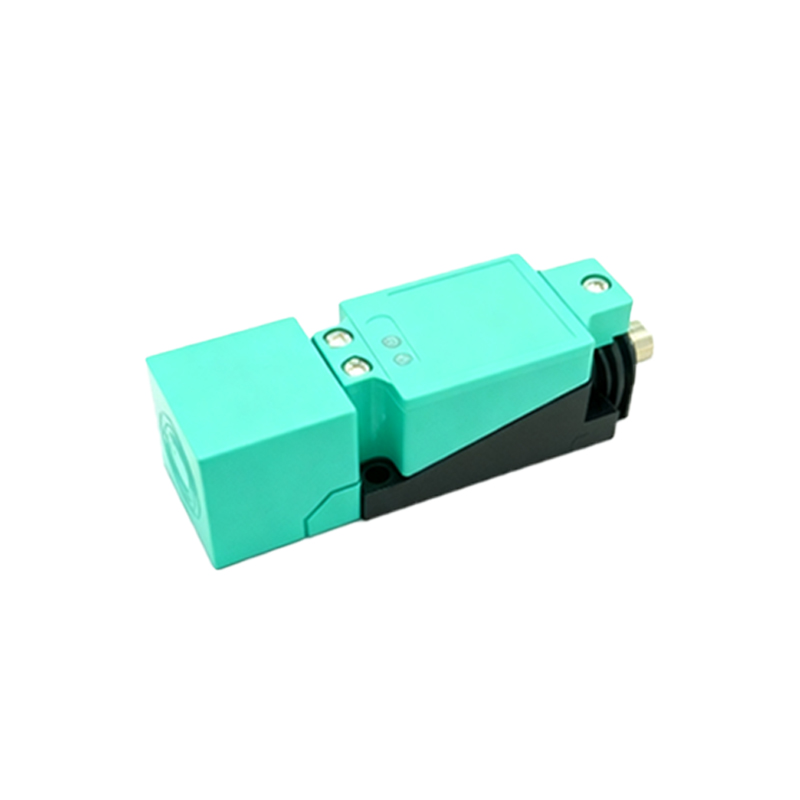
1. Incorrect Sensor Selection or Application: This is often the foundational error. Using a sensor with an insufficient sensing distance for the application is common. The rated sensing distance (Sn) is defined for a standard mild steel target. Factors like target size (must be equal to or greater than the sensor's active face), shape, and the specific type of ferrous material (e.g., stainless steel, cast iron) can significantly reduce the effective sensing range. A sensor chosen with minimal margin for error will fail with minor misalignments or material variations.
2. Mechanical Misalignment and Mounting Issues: Proper installation is critical. Even a correctly specified sensor will fail if the target does not pass through its effective sensing zone. Angular misalignment, excessive gap between the sensor face and the target path, and vibration causing physical movement of the sensor or target are typical culprits. Additionally, flush-mountable sensors installed in non-ferrous metal housings perform optimally, while non-flush sensors require specific clearance from surrounding metal to avoid false triggering or shielding effects.
3. Environmental Contaminants and Sensor Face Obstruction: Industrial environments are harsh. Accumulation of metal chips, dust, grease, or other debris on the active face of the sensor can attenuate the electromagnetic field, effectively reducing its sensing capability. A thin, consistent layer of ferrous dust can sometimes cause the sensor to latch in the "on" state, while non-conductive buildup can insulate the sensor from the target.
4. Electrical and Wiring Faults: While seemingly basic, wiring problems account for a significant percentage of field issues. These include loose connections, damaged cables, incorrect voltage supply (e.g., applying 24VDC to a 10-30VDC sensor is fine, but reverse polarity is not), and excessive voltage drops over long wire runs. The load connected to the output (e.g., a PLC input, relay coil) must also be within the sensor's switching capacity. An overloaded output may not fail completely but can behave erratically.
5. Sensor Degradation or Internal Failure: Proximity switches are robust but not immortal. Internal components, such as the oscillator coil, can degrade due to prolonged exposure to extreme temperatures, voltage spikes, or physical shock. Moisture ingress, leading to corrosion on the PCB, is another common failure mode, especially in wash-down environments if the sensor's IP rating is inadequate.
6. Electrical Noise Interference: In panels with variable frequency drives (VFDs), solenoids, motors, and high-current switching devices, electromagnetic interference (EMI) can disrupt the sensitive circuitry of a proximity sensor. This can manifest as erratic switching, failure to detect, or constant oscillation. Noise can be conducted through power lines or induced into signal cables.
Systematic Diagnostic Approach:
A logical, step-by-step diagnosis is essential to avoid misdiagnosis and unnecessary part replacement.
Step 1: Visual and Physical Inspection. Check for obvious physical damage, contamination on the sensor face, and verify the target is present, correctly sized, and made of appropriate material. Confirm mechanical alignment and mounting stability.
Step 2: Electrical Verification. Using a multimeter, verify the supply voltage at the sensor's terminals under load. Check for correct polarity. Measure the output voltage when the target is presented and absent. For a sinking (NPN) sensor, you should see a voltage close to supply when "off" and near 0V when "on" (to the positive lead). The opposite is true for sourcing (PNP) sensors.
Step 3: Operational Check. Many modern sensors have a built-in LED status indicator. Observe its behavior. A solid LED when a target is present typically indicates