Capacitive proximity sensors are essential components in modern industrial automation, offering non-contact detection of various objects regardless of material composition. This article provides a detailed visual and technical exploration of capacitive proximity sensors through images and diagrams, explaining their operational principles, typical applications, and key selection criteria.
Images of capacitive proximity sensors reveal a compact, cylindrical or rectangular housing, often constructed from stainless steel, nickel-plated brass, or PBT plastic. A cross-sectional diagram is particularly instructive. It shows the key internal components: the active electrode (sensing face), the guard electrode (surrounding the active electrode), the oscillator circuit, the trigger circuit, and the output switching device. The sensor face is typically covered by a dielectric material, forming the sensing surface. The guard electrode's crucial role is to focus the electrostatic field forward, minimizing side and rear sensitivity and creating a well-defined detection zone.
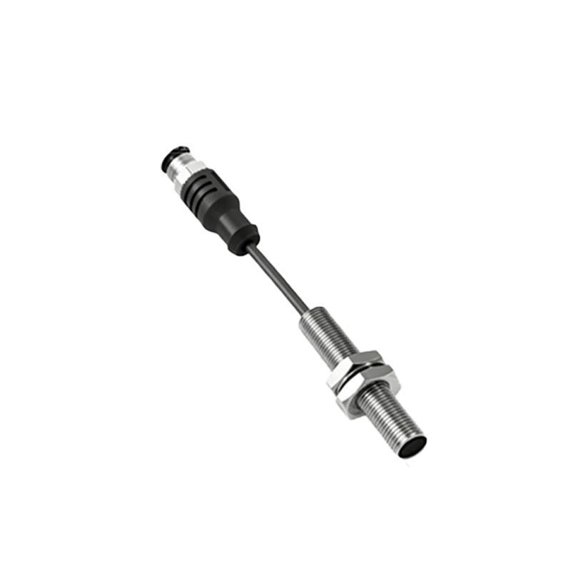
The operating principle, best understood through functional diagrams, relies on capacitance change. The active electrode and the target object form a capacitor. The internal oscillator generates an electrostatic field emanating from the sensing face. When a target object enters this field, it alters the dielectric constant and the capacitance of the system. This change in capacitance increases the oscillator's amplitude. The trigger circuit monitors this amplitude, and once it reaches a preset threshold, it commands the output circuit (typically an NPN or PNO transistor) to switch states. An animated sequence of images effectively demonstrates this process: first, the sensor in standby with a stable field; then, a target (e.g., a liquid container) approaching; and finally, the field distortion triggering the output signal, often indicated by an LED on the sensor body illuminating.
A collection of application photos showcases the sensor's versatility. Common examples include:
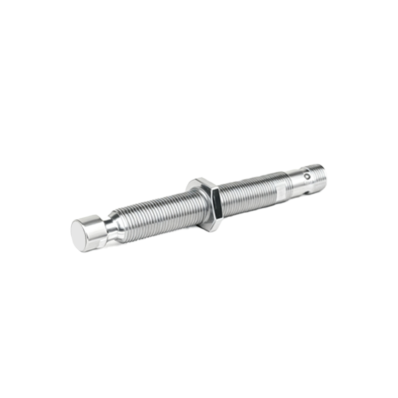
1. Liquid Level Detection: An image shows a sensor mounted on the exterior of a non-metallic tank (plastic or glass) detecting the level of water or chemical fluids without direct contact, highlighting its ability to sense through container walls.
2. Material Presence Detection: A photo from a packaging line depicts a sensor verifying the presence of cardboard boxes on a conveyor, even if the boxes are empty.
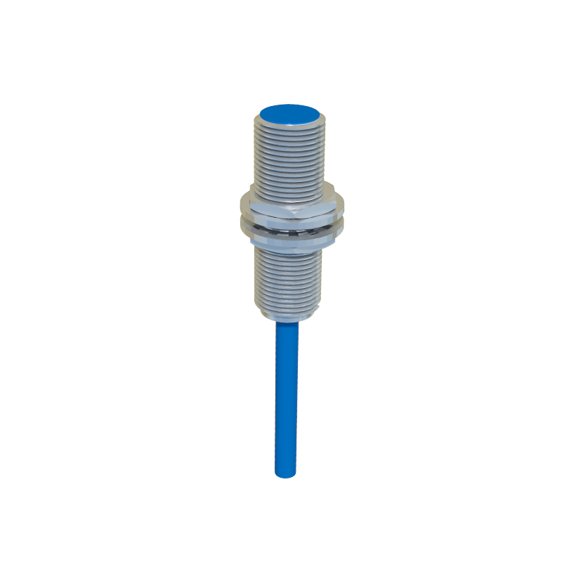
3. Granule or Powder Detection: An installation image in a hopper shows a sensor monitoring the fill level of plastic pellets or flour, preventing overfill or run-out.
4. Non-Metal Object Detection: A close-up in an assembly station shows a sensor reliably detecting wooden blocks or plastic components.
Key specifications are often summarized in labeled product images or specification sheet graphics. Critical parameters visible or indicated include:
- Sensing Distance (Sn): Rated operating distance, typically from 2mm to 40mm for standard models. Diagrams show the defined sensing range.
- Housing Style: Images differentiate between cylindrical (e.g., M8, M12, M18, M30 threads) and rectangular block styles.
- Output Type: Icons or wiring diagrams indicate NPN (sourcing), PNP (sourcing), or NO/NC contacts.
- Connection Method: Photos show pre-wired cables or quick-disconnect (connector) variants.
- Indicator LED: A bright LED, visible in application photos, shows output status.
- Material and IP Rating: Labels indicate housing material (e.g., V2A stainless steel) and Ingress Protection rating like IP67 or IP69K for harsh environments.
When selecting a sensor, reference images comparing installation scenarios are vital. A diagram illustrating the correct and incorrect mounting of flush-mountable sensors is crucial. Flush-mounted sensors can be installed embedded in metal without false triggering, whereas non-flush sensors require a free space around the sensing face. Another comparative image set demonstrates the influence of the target material and size on the actual sensing range. For instance, a large conductive target (metal) achieves the full nominal range, while a non-conductive target (plastic) or a smaller target reduces the effective sensing distance. This is often quantified in correction factor graphs.
In conclusion, capacitive proximity sensor images and technical diagrams are indispensable tools for engineers. They bridge the gap between theoretical data sheets and practical implementation, providing clear insights into design, functionality, and optimal application. From internal circuitry to real-world installation photos, this visual information ensures correct sensor selection, reliable system integration, and efficient troubleshooting in diverse industrial settings, from food and beverage processing to pharmaceutical manufacturing and material handling.