In the realm of industrial automation and control systems, proximity switch sensors stand as fundamental components for non-contact detection. Among the various installation methods, the insertion or embedment of these sensors is a critical procedure that demands precision and understanding. This guide delves into the technical nuances of correctly inserting proximity sensors, ensuring optimal performance, longevity, and system reliability.
Proximity sensors, including inductive, capacitive, and photoelectric types, are designed to detect the presence or absence of an object without physical contact. The insertion method typically refers to mounting the sensor into a pre-drilled hole in a metal bracket, machine frame, or housing, often with the sensing face flush or recessed. This approach protects the sensor from mechanical damage, environmental contaminants, and electromagnetic interference, which is crucial in harsh industrial environments like assembly lines, packaging machinery, and robotic cells.
The process begins with meticulous planning. Engineers must first consult the sensor's datasheet for precise dimensional specifications, including the required mounting hole diameter, thread specifications (if applicable), and necessary clearances around the sensing area. A common standard involves machining a hole with a tolerance of H7 or as specified by the manufacturer. An incorrectly sized hole—too tight or too loose—can lead to installation stress, inaccurate sensing, or even sensor failure. For inductive sensors, which detect metallic objects, special attention must be paid to the "flush-mountable" designation. Flush-mountable sensors can be installed embedded in metal without affecting their sensing range, whereas non-flush types require a specific clearance zone free of surrounding metal to function correctly.
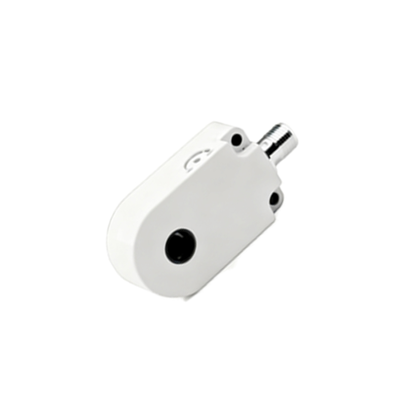
Prior to insertion, the installation site must be prepared. This involves deburring the machined hole to remove any sharp edges that could damage the sensor's housing or cable. The area should be clean, free of metal chips, oil, or dust. For sensors with threaded barrels, applying a moderate amount of appropriate thread-locking compound can prevent loosening due to vibration, a frequent issue in dynamic industrial settings. However, caution is advised to avoid contaminating the sensing face.
The actual insertion requires care. Sensors should never be forced into place using excessive hammering or torque on the cable. For cylindrical sensors, a gentle, straight push or a precise turn with a wrench on the hex nut (if provided) is sufficient. O-rings or gaskets, often included for environmental sealing (e.g., IP67 rating), must be correctly seated to maintain the integrity of the seal against liquids and particulates. During this phase, cable management is paramount. The sensor's cable or connector must be routed away from moving parts, high-temperature surfaces, and sources of electrical noise like motor drives or power lines. Sharp bends at the cable entry point must be avoided to prevent wire fatigue and breakage.
Post-insertion, alignment and testing are non-negotiable. The sensing face must be properly oriented towards the target object's path. The gap between the sensor and the target, known as the operating distance, should be set to 50-80% of the sensor's nominal sensing range to account for mechanical tolerances and temperature drifts. Functional testing involves using the actual target material to verify reliable detection across all operational conditions. Engineers should use a multimeter or the PLC's input indicators to confirm a clean, stable switching signal without chatter.
Troubleshooting insertion-related issues often involves checking for improper mounting (e.g., non-flush sensor in a flush application), insufficient clearance, accumulation of metallic dust on the sensing face, or damage to the housing during installation. Regular maintenance schedules should include visual inspections of the sensor's position and seal integrity.
In conclusion, the insertion of a proximity switch sensor is far more than a simple mechanical task. It is a systematic engineering practice that integrates knowledge of sensor technology, mechanical design, and environmental considerations. Adhering to manufacturer guidelines and industry best practices during insertion is a direct investment in reducing downtime, enhancing safety, and ensuring the seamless operation of automated systems. As technology advances with IO-Link and smart sensors, proper physical installation remains the foundational step upon which all advanced diagnostics and data communication rely.