In industrial automation and control systems, proximity sensors are indispensable components for non-contact object detection. Among the various wiring configurations, the 3-wire setup is the most prevalent for DC-powered sensors due to its balance of functionality, reliability, and simplicity. This article provides a detailed technical explanation of the standard 3-wire proximity sensor circuit, its operation, and key considerations for implementation.
A typical 3-wire DC proximity sensor has three distinct leads, usually color-coded as Brown, Blue, and Black (or sometimes White). This color scheme is largely standardized per international conventions (e.g., IEC 60947-5-2), though it is crucial to always verify the specific manufacturer's datasheet. The Brown wire is connected to the positive DC supply voltage (V+), commonly 10-30 VDC. The Blue wire is connected to the common negative or 0V (V-) of the DC supply. The third wire, Black (or White), is the signal output line. This output can be either NPN (sinking) or PNP (sourcing) configuration, which fundamentally defines the circuit's switching logic and compatibility with the controller.
Let's dissect the two primary circuit types. First, the PNP (Sourcing) 3-Wire Circuit. In this configuration, the sensor's internal switching element is a PNP transistor. When the sensor is inactive (no target detected), the output transistor is off, and the Black wire is electrically disconnected from the internal positive supply. The output signal line is effectively floating or pulled low through a controller's internal resistor. When a target enters the sensing range, the sensor activates, turning the PNP transistor on. This action connects the Black output wire internally to the positive supply (Brown wire). Thus, the sensor sources current from the supply to the load. The load (e.g., a PLC input, relay coil, or indicator lamp) is connected between the Black output wire and the negative supply (Blue wire). Voltage appears across the load, completing the circuit.
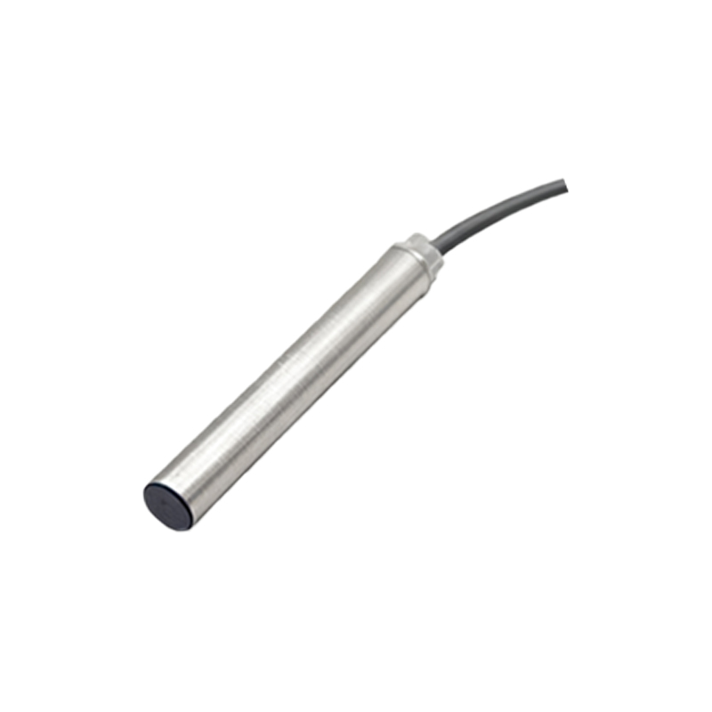
Conversely, the NPN (Sinking) 3-Wire Circuit uses an NPN transistor as the switching element. Here, the wiring for Brown (V+) and Blue (V-) remains identical. The critical difference lies in the output and load connection. In the inactive state, the NPN transistor is off, leaving the Black output wire disconnected from the internal circuit. Upon target detection, the NPN transistor turns on. This internally connects the Black output wire to the negative supply (Blue wire). The sensor now sinks current from the load to ground. Therefore, the load must be connected between the positive supply (Brown) and the Black output wire. The active sensor completes the path to ground, allowing current to flow through the load.
Understanding the distinction between PNP (sourcing) and NPN (sinking) is paramount for system compatibility. Many Programmable Logic Controllers (PLCs) from regions like Europe are designed for PNP input cards (sensing a positive voltage), while NPN is common in other areas. Connecting an NPN sensor to a PNP-designed input, or vice versa, will result in malfunction. A simple way to remember is: PNP = Positive-switched, NPN = Negative-switched.
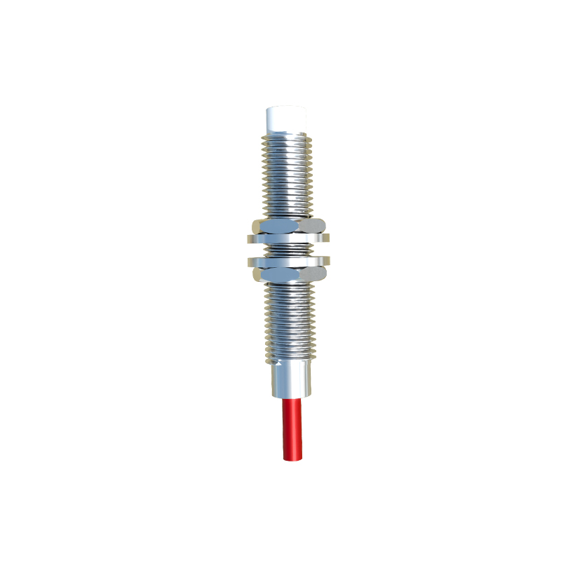
The circuit diagram also includes essential protection and stabilization components not always visible to the user. Internally, the sensor contains a voltage regulator to provide stable power for the oscillator and amplifier circuits. A reverse polarity protection diode is often included across the supply terminals to prevent damage if Brown and Blue are accidentally swapped. The output transistor is protected by a flyback or clamping diode, especially critical when driving inductive loads like relays to suppress voltage spikes. An LED indicator, in series with a current-limiting resistor, is connected in parallel to the output to provide visual status.
For reliable operation, several practical wiring considerations must be observed. Always use a stable, regulated DC power supply within the sensor's specified range (e.g., 24 VDC ±10%). Ensure proper grounding and use twisted-pair or shielded cables for longer runs in electrically noisy environments to prevent electromagnetic interference (EMI) from causing false triggering. The load connected to the output must not exceed the sensor's maximum switching current and voltage ratings. If the load is highly inductive, an external suppression circuit (like a freewheeling diode) across the load is recommended. Finally, adhere to standard industrial safety practices, including lockout-tagout procedures, during installation and maintenance.
In summary, the 3-wire proximity sensor circuit offers a robust and straightforward interface for industrial controls. Its design, centered on either a PNP or NPN output transistor, dictates the current-sourcing or sinking behavior and the necessary load connection topology.