In the realm of industrial automation and control, the ability to detect the presence, absence, or position of an object without physical contact is paramount. Among the various technologies enabling this capability, Hall Effect proximity sensors stand out for their reliability, durability, and versatility. As an electrical engineer with extensive field experience, I aim to provide a comprehensive overview of these essential components, from their fundamental operating principles to practical application considerations.
The core principle behind a Hall Effect sensor is a classical phenomenon discovered by Edwin Hall in 1879. When a current-carrying conductor or semiconductor is placed perpendicular to a magnetic field, a voltage difference, known as the Hall voltage, is generated across the material. This voltage is proportional to the strength of the applied magnetic field. A Hall Effect proximity sensor leverages this principle by integrating a Hall element, signal conditioning circuitry, and often a digital output stage into a single package. When a ferromagnetic target (like a gear tooth or a machine part) or a permanent magnet approaches the sensor face, it disturbs or introduces a magnetic field. This change is detected by the Hall element, and the internal electronics process the signal to trigger a clean, digital output switch.
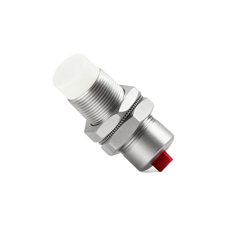
This operating principle grants Hall Effect sensors several distinct advantages. First, they are true solid-state devices with no moving parts, leading to exceptional longevity and resistance to mechanical wear. They can operate at very high switching frequencies, often in the hundreds of kilohertz range, making them ideal for speed detection on rotating shafts (e.g., in brushless DC motors or for RPM measurement). Their performance is largely unaffected by environmental contaminants such as dust, oil, moisture, or vibrations, which are common in industrial settings. Unlike inductive sensors, which primarily detect ferrous metals, Hall Effect sensors can be configured to detect both the presence and the polarity of a magnetic field, allowing for more complex positional encoding.
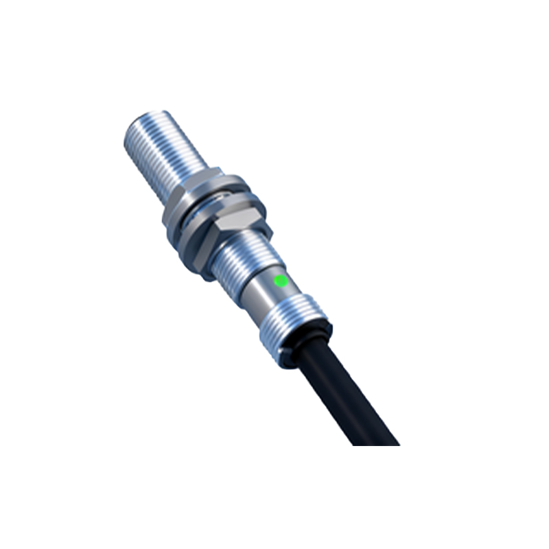
The applications for Hall Effect proximity sensors are vast and critical across numerous industries. In automotive systems, they are ubiquitous in anti-lock braking systems (ABS) for wheel speed sensing, in transmission systems for gear position detection, and in electric power steering for torque measurement. Within industrial machinery, they serve as limit switches, provide feedback in linear actuators, and ensure precise angular positioning in robotic arms. In the consumer electronics sector, they enable the smart flip covers on laptops and tablets, detecting when the lid is closed. A particularly common application is in BLDC motor commutation, where multiple sensors provide the necessary rotor position feedback for the electronic controller to sequence the windings correctly.
When selecting a Hall Effect sensor for a specific application, engineers must carefully evaluate several key parameters. The first is the sensing distance or switch point, which must be specified in relation to the strength and geometry of the target magnet or ferrous object. Output type is crucial: digital outputs (open-collector, push-pull, or current sinking/sourcing) are common for simple on/off detection, while analog outputs provide a voltage proportional to the magnetic field strength for precise position measurement. The operating voltage range (e.g., 3.3V, 5V, or 10-30V DC) must match the control system's supply. Temperature range is another critical factor, especially for applications under the hood of a vehicle or in foundries. Engineers must also consider the sensor's housing material (e.g., PBT plastic, stainless steel) and ingress protection (IP) rating to ensure it can withstand the specific environmental conditions, including exposure to chemicals, coolants, or high-pressure washdowns.
Installation and configuration also demand attention. Proper alignment between the sensor and the target is essential for consistent operation. Shielding from stray magnetic fields from nearby motors or transformers may be necessary to prevent false triggering. For speed sensing applications using a ferrous gear, the relationship between gear tooth size, sensor gap, and the required switching frequency must be calculated to avoid signal dropout.
Looking ahead, the evolution of Hall Effect technology continues. Integrated circuit advancements have led to the development of highly sensitive, programmable sensors with built-in diagnostics and temperature compensation. 3D Hall sensors, capable of detecting magnetic field vectors in multiple axes, are opening new frontiers in complex motion control and joystick applications. The inherent robustness and contactless nature of Hall Effect sensing ensure its continued dominance in scenarios demanding high reliability. For any engineer designing motion control, safety interlock, or precision measurement systems, a deep understanding of Hall Effect proximity sensors is not just beneficial—it is fundamental to creating robust, efficient, and intelligent industrial solutions.