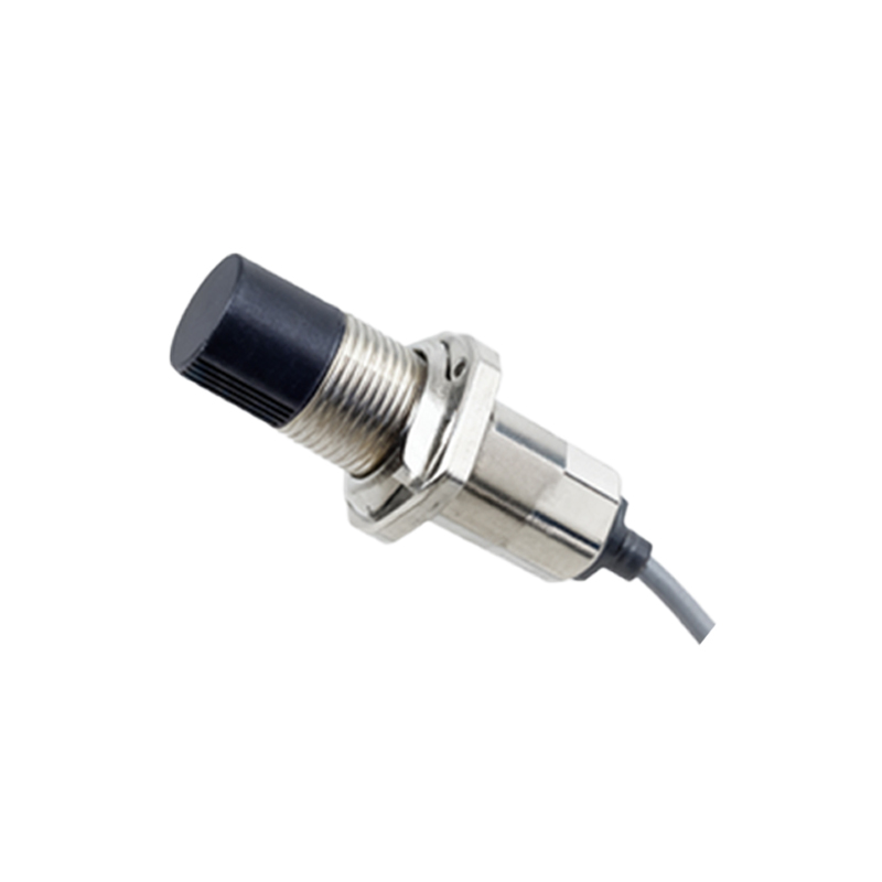
Proximity sensors are essential components in modern industrial automation, providing non-contact detection of objects within a specific range. The control circuit design for these sensors is critical to ensuring reliable operation, accuracy, and integration with broader systems. This article delves into the key aspects of designing and implementing proximity sensor control circuits, covering common types, circuit configurations, and practical considerations.
Proximity sensors primarily fall into three categories: inductive, capacitive, and photoelectric. Inductive sensors detect metallic objects using electromagnetic fields, while capacitive sensors respond to both metallic and non-metallic materials by sensing changes in capacitance. Photoelectric sensors use light beams to detect objects. Each type requires a tailored control circuit to optimize performance. The core of a proximity sensor circuit typically includes an oscillator, signal conditioner, output stage, and power supply unit.
For inductive proximity sensors, the control circuit often features an LC oscillator that generates a high-frequency electromagnetic field. When a metal object enters this field, eddy currents are induced, causing a change in oscillation amplitude. This change is detected by an amplitude demodulation circuit, which converts it into a usable signal. The signal then passes through a comparator or Schmitt trigger to produce a clean digital output—either NPN (sinking) or PNP (sourcing)—compatible with PLCs or microcontrollers. Key components include a stable oscillator coil, precision resistors for sensitivity adjustment, and protection diodes to guard against voltage spikes.
Capacitive sensor circuits operate similarly but use a capacitive plate to generate an electric field. The circuit measures capacitance changes when an object alters the dielectric constant. This requires a high-frequency oscillator and sensitive detection circuitry, often incorporating adjustable potentiometers for threshold calibration. Shielding is crucial to minimize false triggers from environmental factors like humidity or dust.
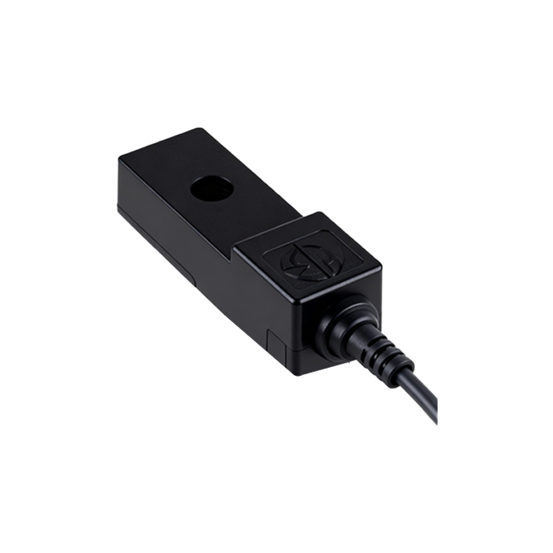
Photoelectric sensors employ an LED or laser diode as a light source and a phototransistor or photodiode as a receiver. The control circuit must regulate current to the emitter and amplify the receiver's signal. Ambient light interference can be mitigated using modulated light signals and synchronous detection techniques. Output stages may include analog outputs for distance measurement or digital outputs for simple detection.
Power supply design is vital for all proximity sensor circuits. Most industrial sensors operate on 12-24V DC, with built-in voltage regulators and reverse-polarity protection. Noise immunity can be enhanced by adding filtering capacitors and ferrite beads. For harsh environments, consider surge protection devices and conformal coating on PCBs.
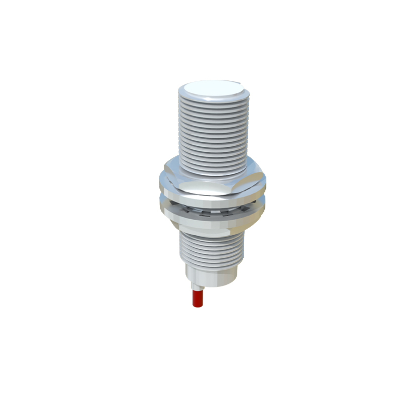
When implementing these circuits, follow best practices: use short, shielded cables to reduce electromagnetic interference; ensure proper grounding to avoid ground loops; and adhere to IP ratings for enclosure selection. Testing with actual target objects under operational conditions helps fine-tune sensitivity and response time. Integration with control systems often requires output signal conditioning, such as optocoupler isolation for high-voltage applications.
In summary, a well-designed proximity sensor control circuit balances sensitivity, stability, and durability. By understanding the sensor type and application requirements, engineers can create robust solutions that enhance automation efficiency. Future trends include smart sensors with integrated diagnostics and IoT connectivity, but the fundamental circuit principles remain rooted in reliable detection and signal processing.