In industrial automation and electrical control systems, proximity sensors are ubiquitous components, silently detecting the presence or absence of objects without physical contact. As an electrical engineer or technician, a common troubleshooting question arises: can you effectively test a proximity sensor using a standard digital multimeter (DMM)? The answer is a qualified yes, but with important caveats and a clear understanding of the sensor's type and operating principles.
A multimeter is an invaluable tool for basic electrical diagnostics. For proximity sensors, it can help verify power supply integrity, check output state continuity, and, in some cases, assess basic functionality. However, it is crucial to remember that a standard DMM cannot replicate the dynamic sensing conditions or measure the precise sensing distance. Its role is primarily for static, point-in-time checks.
The testing approach depends entirely on the sensor's technology and output configuration. The two most common types are Inductive (detecting metallic objects) and Capacitive (detecting both metallic and non-metallic objects), each with DC or AC power variants and different output types: NPN (sinking), PNP (sourcing), or Analog.
Testing a 3-Wire DC Proximity Sensor (NPN or PNP):
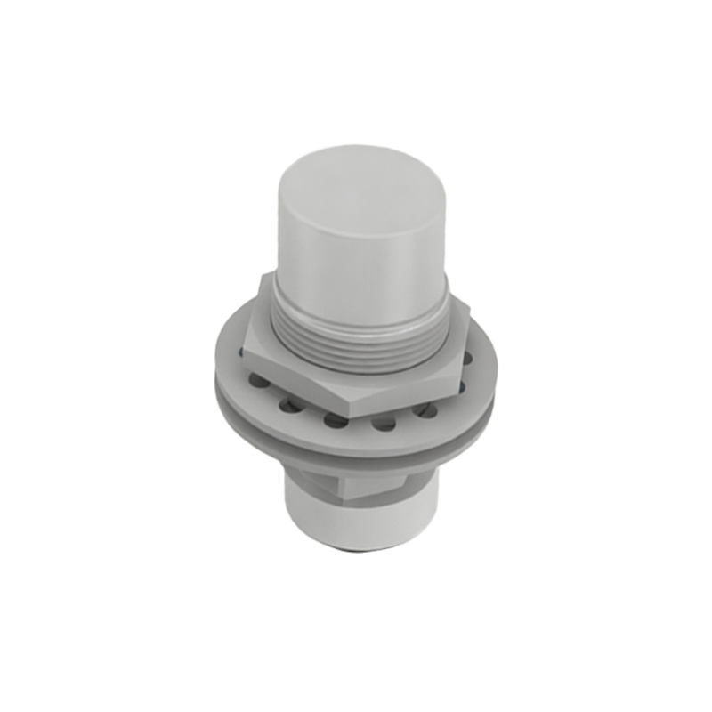
This is the most straightforward scenario for multimeter use.
1. Power Verification: With the sensor disconnected or powered down, set your DMM to DC voltage. Connect the sensor's brown wire (typically +V, e.g., 10-30V DC) and blue wire (typically 0V/Common) to the correct power supply. Power up. Measure the voltage between the brown and blue wires. It should be within the sensor's specified range (e.g., 24V DC ±10%).
2. Output State Check: This is the core test. Set the DMM to measure DC voltage. With the sensor powered:
No Target Present: Measure the voltage between the black wire (output) and the blue wire (0V). For a PNP (sourcing) sensor, you should read near the full supply voltage (e.g., ~24V). For an NPN (sinking) sensor, you should read a very low voltage (near 0V).
Target Present: Introduce the correct target material (e.g., a piece of steel for an inductive sensor) within the sensor's specified sensing distance.
For a PNP sensor, the voltage between the black and blue wires should now drop to near 0V (the output is "active low," sinking current to common).
For an NPN sensor, the voltage should rise to near the supply voltage (the output is "active high," sourcing current from the supply).
A change in voltage state confirms the switching action is working. You can also use the DMM's continuity or resistance mode (with power OFF) to check for a short circuit between wires, but the voltage test under load is more definitive.
Testing a 2-Wire AC/DC Proximity Sensor:
These sensors act like a switch in series with the load. Testing requires caution due to possible AC voltage.
1. Power OFF & Disconnect: Ensure the circuit is de-energized.
2. Resistance Check: Set the DMM to a high resistance range (e.g., 200kΩ). Connect the probes to the two sensor wires.
No Target: The resistance should be very high (open circuit or leakage current level).
Target Present: The resistance should drop significantly (closed circuit, though not necessarily 0Ω due to internal electronics). This indicates the switching element is functioning.
Warning: Do not perform this resistance test while the sensor is powered, as it can damage the meter.
Important Limitations and Best Practices:
No Sensing Range Verification: A DMM cannot tell you if the sensor triggers at 5mm or 8mm. Only a calibrated target and distance gauge can verify the rated sensing distance.
Load Simulation: For a conclusive test, the sensor output should be connected to its intended load (e.g., a PLC input, relay coil). A DMM has very high input impedance. Some sensors might behave correctly with a DMM but fail to drive an actual load due to internal output transistor issues. Observing the load's operation is the ultimate test.
Analog Sensors: For 4-20mA or 0-10V analog output sensors, a DMM can measure the output current (in series) or voltage. You can check if the output changes proportionally with target distance, but again, calibration requires precise positioning.
Safety First: Always follow lock-out/tag-out (