Two-wire proximity sensors are fundamental components in modern industrial automation, offering a simplified solution for object detection without physical contact. Unlike their three-wire counterparts, these sensors integrate the switching element directly into the power line, resulting in a more compact design and easier installation. Understanding the correct wiring diagram is crucial for ensuring reliable operation, safety, and optimal performance in various applications, from conveyor systems to machine guarding.
The core principle of a two-wire AC or DC sensor is that it operates in series with the load it controls, typically a programmable logic controller (PLC) input or a relay coil. There is no separate supply wire and output wire; the same two wires carry both the power for the sensor's internal circuitry and the switched current for the load. This design inherently provides a leakage current, even when the sensor is in the "off" state, which is a critical factor to consider during system design.
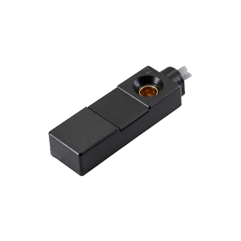
A standard wiring diagram for a two-wire sensor is straightforward. The sensor has two terminals, usually labeled as 1 and 2 or L+ and L-. For an AC sensor, one wire connects to the phase (hot) conductor, and the other wire connects to the load. The load's other terminal then connects to the neutral line, completing the circuit. For a DC sensor, one wire connects to the positive DC supply, and the other connects to the load, which then returns to the negative supply. It is vital to consult the manufacturer's datasheet for specific terminal designations and voltage ratings.
One of the most important considerations is the residual current or leakage current. When the sensor's output is in the off state, a small current (typically a few milliamps) still flows through the circuit to power the sensor's internal electronics. If this current is sufficient to energize a highly sensitive load (like some PLC digital inputs), it may cause a malfunction, making the load appear permanently "on." To prevent this, a bleeder resistor or load resistor is often connected in parallel with the load. This resistor provides an alternative path for the leakage current, ensuring the voltage across the load remains below its activation threshold when the sensor is off. The resistor value must be calculated based on the sensor's specified leakage current and the load's minimum operating current.

Another key aspect is load compatibility. The sensor's datasheet specifies the maximum and minimum load current it can switch. Operating below the minimum load current can lead to unreliable switching, while exceeding the maximum current will damage the sensor. Always verify that the total current draw of the connected load (including any parallel bleeder resistor) falls within the sensor's specified range. For inductive loads like relay coils, the use of a protective circuit, such as a flyback diode for DC or a varistor for AC, is recommended to suppress voltage spikes that could damage the sensor.
Wiring practices significantly impact performance. Use shielded cables in electrically noisy environments, connecting the shield to ground at only one end to prevent ground loops. Keep sensor cables separate from high-voltage power lines to avoid electromagnetic interference. Ensure tight connections to prevent voltage drops and intermittent operation.
In summary, the simplicity of the two-wire proximity sensor wiring diagram belies the need for careful planning. Key steps include: verifying voltage type (AC/DC), calculating and installing a bleeder resistor if necessary, confirming load current compatibility, and implementing proper wiring techniques for noise immunity. By adhering to these guidelines and the manufacturer's instructions, engineers and technicians can ensure robust and trouble-free integration of these versatile sensors into any industrial control system, enhancing both efficiency and safety on the plant floor.