Proximity level sensors are critical components in industrial automation and process control systems, providing reliable detection of liquid levels in tanks, vessels, and pipelines. Proper calibration and debugging are essential to ensure accurate measurements, prevent false triggers, and maintain system integrity. This article outlines systematic methods for calibrating and troubleshooting proximity level sensors, focusing on capacitive, inductive, and ultrasonic types commonly used in electrical and process engineering.
Calibration begins with understanding the sensor's operating principle. Capacitive sensors detect changes in dielectric constant between the sensor probe and the target liquid. Inductive sensors are suitable for conductive liquids, relying on electromagnetic field disturbances. Ultrasonic sensors measure the time-of-flight of sound waves reflected from the liquid surface. Before calibration, verify the sensor's specifications, including sensing range, output type (e.g., analog 4-20mA, digital PNP/NPN), and environmental ratings (e.g., IP67 for waterproofing).
Step 1: Installation Check
Ensure the sensor is mounted correctly, with the sensing face oriented toward the liquid and free from obstructions. For capacitive sensors, avoid contact with tank walls to prevent stray capacitance. Inductive sensors require grounding in metallic tanks to reduce noise. Ultrasonic sensors must be positioned to avoid foam or turbulence, which can scatter signals. Use a level gauge or manual dip measurement as a reference for initial accuracy assessment.
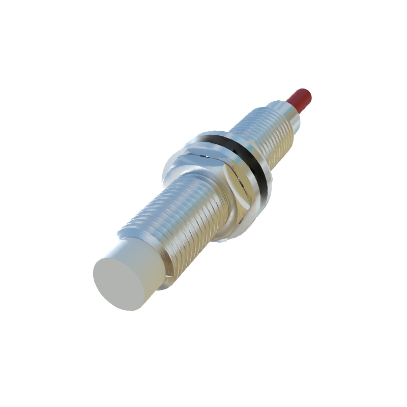
Step 2: Zero and Span Calibration
For analog output sensors, perform zero and span adjustments. With the tank empty, adjust the zero point to set the output at 4mA (or 0V for voltage output). Fill the tank to the maximum level and adjust the span to achieve 20mA (or 10V). Repeat this process twice to ensure stability. Digital sensors often feature teach-in functions: press the calibration button at empty and full levels to store thresholds in memory. Document calibration values for future reference.
Step 3: Environmental Compensation
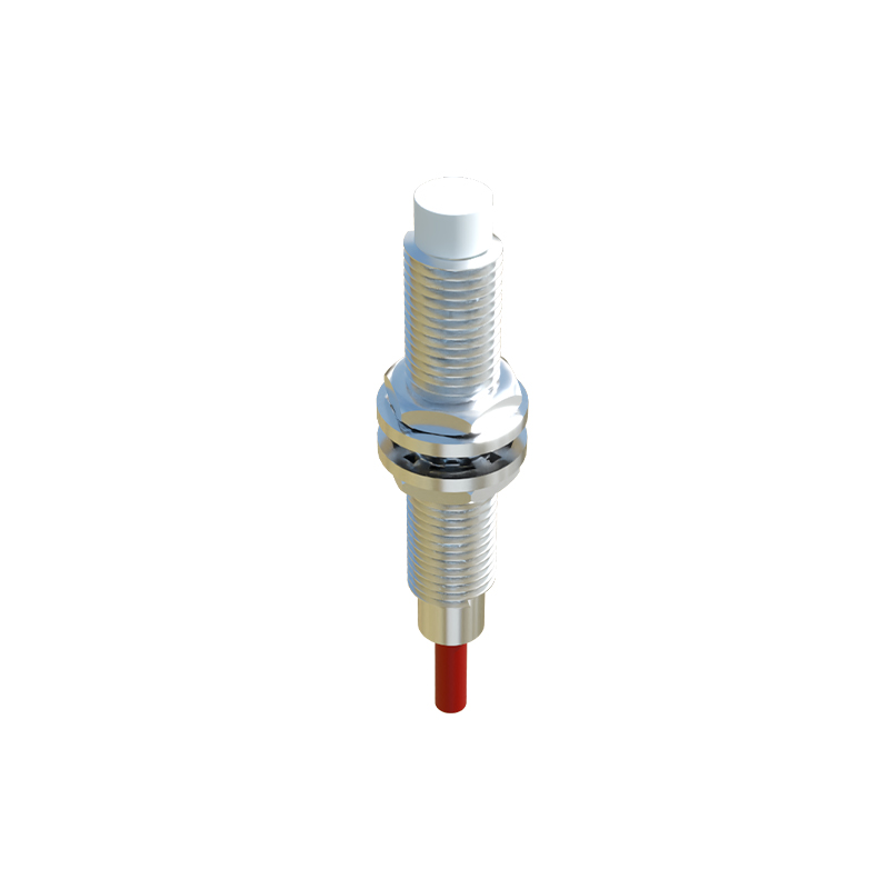
Temperature and humidity affect sensor performance. Compensate by using sensors with built-in temperature correction or installing external compensators. For capacitive sensors in varying dielectric conditions, adjust the sensitivity knob to avoid false detection from adhesive buildup or container material changes. In noisy electrical environments, shield cables and use twisted-pair wiring to minimize interference.
Step 4: Debugging Common Issues
If the sensor fails to detect levels accurately, follow a troubleshooting flowchart. First, check power supply voltage (typically 12-24V DC) and current draw with a multimeter. Inspect wiring for loose connections or shorts. For false triggers, examine the sensing area for contaminants or air bubbles, and clean the probe with a soft cloth and isopropyl alcohol. Test the output signal using an oscilloscope or PLC input module to verify response time and signal integrity.

For persistent problems, simulate conditions: use a known liquid sample in a test setup to isolate issues. Replace the sensor temporarily to rule out hardware failure. Update firmware if the sensor is smart-enabled, and consult manufacturer datasheets for error codes. Regular maintenance, such as quarterly calibration checks and visual inspections, prolongs sensor life and ensures consistent operation.
Advanced techniques include using simulation software to model sensor behavior under different fluid dynamics or integrating sensors with SCADA systems for real-time monitoring. Always adhere to safety protocols, such as locking out power during maintenance and following hazardous area classifications (e.g., ATEX for explosive atmospheres).
In summary, precise calibration and methodical debugging of proximity level sensors enhance system reliability. By combining technical knowledge with hands-on practices, engineers can optimize performance and reduce downtime in industrial applications.