In the realm of automation, robotics, and smart devices, proximity sensors are the silent sentinels, detecting the presence or absence of objects without physical contact. While much attention is given to the sensing technology itself—be it inductive, capacitive, ultrasonic, or optical—the process of signal reception is equally critical. This stage determines the reliability, accuracy, and responsiveness of the entire sensing system.
At its core, signal reception involves capturing the often faint and noisy electrical response generated by the sensor when an object enters its detection field. For an inductive sensor, this is a change in oscillation amplitude; for a capacitive sensor, a shift in capacitance; for an ultrasonic sensor, an echoed sound wave converted to an electrical signal. The primary task of the reception circuitry is to faithfully amplify, condition, and interpret this raw signal into a clean, decisive digital output—typically a simple HIGH or LOW logic signal that a microcontroller or PLC can understand.
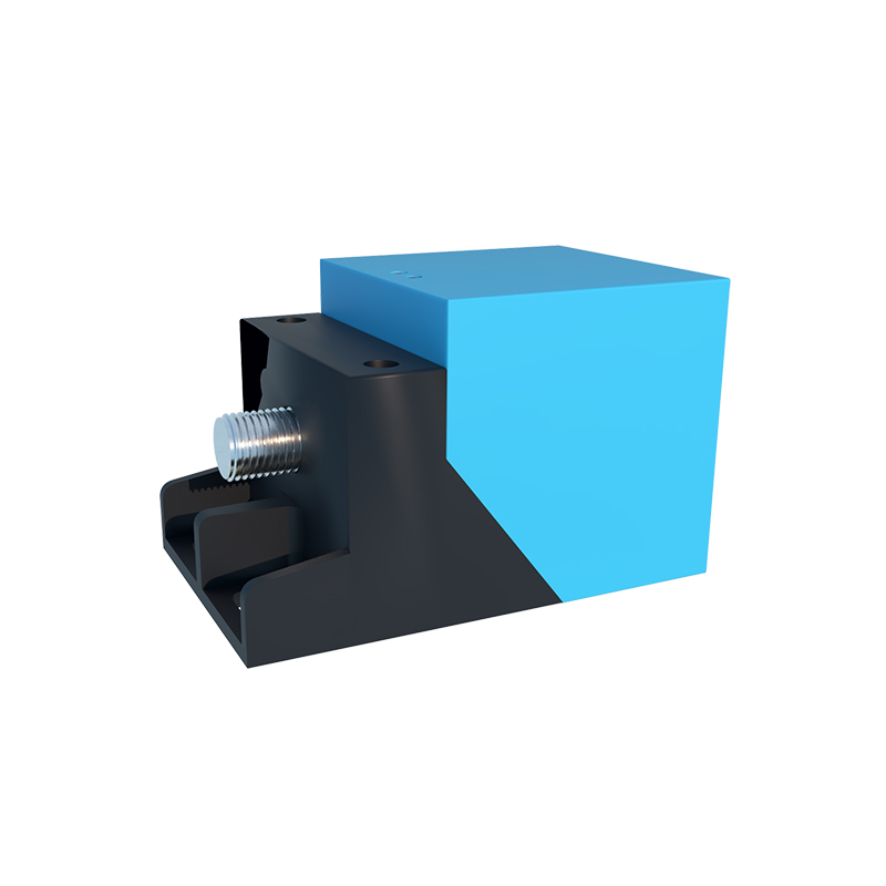
The journey from a raw analog signal to a usable digital command is fraught with challenges. Environmental electrical noise is a pervasive enemy. Motors, relays, power lines, and even other sensors can induce electromagnetic interference (EMI) onto sensor lines, creating false triggers or causing missed detections. Physical environmental factors also play a role. For optical sensors, ambient light, dust, or fog can scatter or absorb the emitted light beam. For ultrasonic sensors, temperature gradients affect sound speed, and acoustic noise or soft, absorbent materials can dampen the echo. Furthermore, the target object itself presents variables: its size, material composition, surface angle, and color can dramatically alter the strength and characteristics of the returned signal.
To overcome these hurdles, sophisticated signal conditioning is employed. This begins with amplification. Operational amplifiers (op-amps) are used to boost the weak sensor signal to a usable voltage level. However, amplifying the signal also amplifies any accompanying noise. This is where filtering becomes essential. Low-pass filters are commonly used to attenuate high-frequency noise from sources like switch-mode power supplies. For sensors susceptible to specific interference bands, band-pass or notch filters can be implemented. Following filtering, the signal often undergoes a process of demodulation (extracting the original information from a carrier wave, common in inductive sensors) or integration to average out short-term noise spikes.
The final, crucial step is threshold comparison. The conditioned analog signal is fed into a comparator circuit. A reference voltage, often adjustable via a potentiometer or digital settings, is set as the detection threshold. When the sensor signal crosses this threshold, the comparator's output switches state, creating the clean digital signal. Setting this threshold correctly is an art—too sensitive, and the system suffers from false positives; too insensitive, and it misses valid detections. Many modern sensors incorporate hysteresis in this stage. Hysteresis introduces two thresholds: one for turning ON and a slightly different one for turning OFF. This prevents rapid, chattering output changes when a target is hovering right at the edge of the detection zone.
Advanced digital signal processing (DSP) techniques are now common in high-end sensors. Microcontrollers with built-in analog-to-digital converters (ADCs) can sample the analog signal thousands of times per second. Algorithms can then analyze this digital data stream to perform tasks like background suppression (ignoring stationary distant objects), pattern recognition to distinguish between target types, and adaptive filtering that adjusts to changing noise environments. Digital communication protocols like IO-Link further enhance reception capabilities by transmitting not just a binary state but detailed parametric data about the signal strength and sensor health.
Optimizing signal reception extends beyond the circuit board. Proper installation and wiring are paramount. Using shielded cables, with the shield properly grounded at one end, is a fundamental defense against EMI. Keeping sensor cables away from power lines and routing them separately in cable trays reduces inductive coupling. Ensuring a stable, clean power supply with adequate decoupling capacitors near the sensor electronics prevents voltage spikes and ripple from corrupting the signal. For optical sensors, keeping lenses clean and aligning the emitter and receiver correctly are simple yet vital practices.
In conclusion, effective proximity sensor operation is not merely about emission but intelligent reception. It is a multi-layered defense against a noisy world, combining analog electronics, digital logic, and sound engineering practices. By understanding the principles of signal conditioning, the sources of interference, and the methods for mitigation, engineers and technicians can ensure that these critical components provide the reliable, unambiguous data that modern automated systems depend on. The quiet efficiency of a well-tuned sensor is, in reality, the product of a sophisticated and resilient signal reception strategy.