Proximity sensors are indispensable components in modern industrial automation, serving as the "eyes" of control systems for non-contact detection of metallic or non-metallic objects. Correct wiring is paramount to ensure reliable operation, safety, and longevity of both the sensor and the connected machinery. This guide provides a detailed, engineer-focused walkthrough of standard proximity sensor wiring configurations, adhering to international conventions and best practices.
Fundamentally, proximity sensors are categorized by their output type and sensing technology. The two primary output types are NPN (sinking) and PNP (sourcing), which dictate the current flow direction. The three-wire DC sensor is the most common industrial configuration, and its wiring is the core of this discussion. The standard wire color coding, though variations exist, typically follows: Brown for positive supply (+V), Blue for common negative (0V), and Black for the switched output signal. White is often used for a complementary output or diagnostic function.
Let's dissect the wiring for a standard 3-wire DC sensor.
1. PNP (Sourcing) Sensor Wiring:
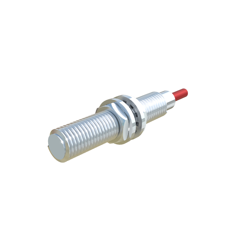
A PNP sensor sources current to the load. When the sensor is activated (target detected), the output switch inside the sensor connects the Black output wire to the positive supply (Brown wire). Current flows from the sensor's Black wire to the load.
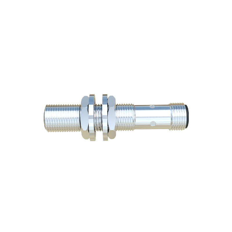
Wiring Procedure: Connect the Brown wire to the DC positive terminal of your power supply (e.g., +24VDC). Connect the Blue wire to the DC negative terminal (0V). The Black output wire is connected to one terminal of your load (e.g., a PLC input, relay coil, or indicator lamp). The other terminal of the load is then connected back to the power supply's negative (0V). This completes the circuit. When a target is present, +24V appears on the Black wire, energizing the load.
2. NPN (Sinking) Sensor Wiring:
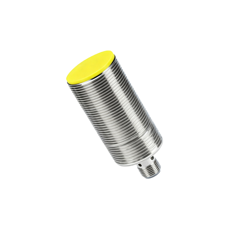
An NPN sensor sinks current from the load. When activated, the output switch connects the Black output wire to the common negative (Blue wire). Current flows from the load into the sensor's Black wire.
Wiring Procedure: Power connections remain identical: Brown to +V, Blue to 0V. The critical difference is in the load connection. One terminal of the load is connected to the positive supply (+V). The other terminal of the load is connected to the sensor's Black output wire. When the sensor activates, it provides a path to 0V, completing the circuit and allowing current to flow through the load into the sensor.
Crucial Considerations for Robust Installation:
Load Placement: Always connect the load (PLC input, relay) directly to the sensor's output wire. Avoid placing the load on the power supply line to the sensor.
Shielded Cable: For environments with significant electromagnetic interference (EMI), use shielded cable. Connect the cable shield to a functional earth ground at the controller end only, avoiding ground loops.
Short-Circuit Protection: Ensure the connected power supply or interface module has built-in protection against output short-circuits, a common feature in industrial sensors.
Leakage Current: Be aware that even in the "OFF" state, a small leakage current (typically<1mA) may flow through solid-state outputs. This can be enough to hold on a highly sensitive PLC input or small relay. Using a bleeder resistor in parallel with the load can mitigate this issue.
2-Wire AC Sensors: These sensors wire in series with the load, similar to a mechanical switch. They are polarity-insensitive. Ensure the load's current draw falls within the sensor's minimum and maximum operating current specifications to guarantee proper turn-on and turn-off.
4-Wire Sensors (Dual Output): These combine both a PNP (NO) and an NPN (NC) output in one device, often with Black and White wires. Wiring follows the same principles for each independent output channel. Always consult the specific datasheet.
Wiring to a PLC Digital Input: Confirm your PLC input card's configuration. Sourcing input cards (common on Allen-Bradley) typically require a sinking (NPN) sensor. Sinking input cards (common on Siemens) typically require a sourcing (PNP) sensor. Mismatching will result in non-operation.
Diagnostic Steps for Fault Finding:
1. Verify Power: Use a multimeter to confirm correct voltage (e.g., 24VDC ±10%) between Brown (+) and Blue (-) wires at the sensor connector.
2. Check Output State: Measure voltage between Black (output) and Blue (0