In the field of industrial automation and electronic circuit design, the deliberate short-circuiting of a sensor is not a standard operational procedure. It is typically a diagnostic, testing, or emergency bypass technique. This article provides a detailed, professional guide on the methodology and critical considerations for short-circuiting an infrared (IR) proximity sensor. It is imperative to understand that this action can permanently damage the sensor and connected circuitry if not performed with explicit intent and proper safety protocols.
Understanding the IR Proximity Sensor Output
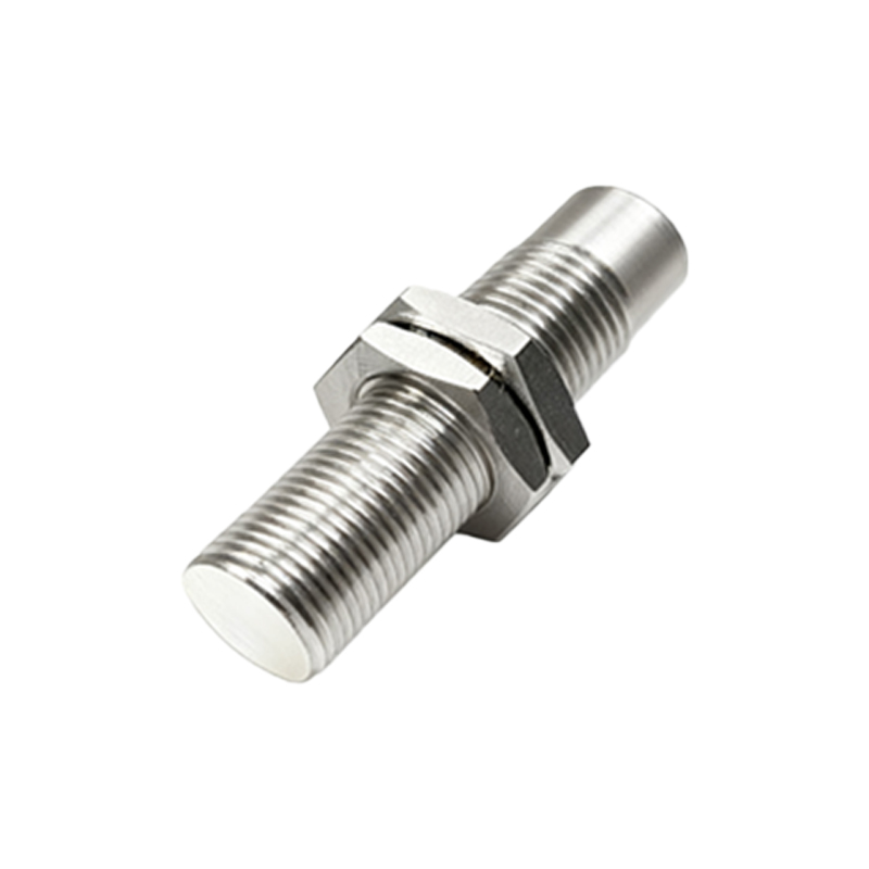
Before any physical intervention, one must comprehend the sensor's output configuration. Most industrial IR proximity sensors provide a digital or analog output signal.
Digital (Switching) Output: These are most common, often in PNP (sourcing) or NPN (sinking) configurations. They act as a solid-state switch, connecting the output line to either the supply voltage (PNP) or ground (NPN) when an object is detected.
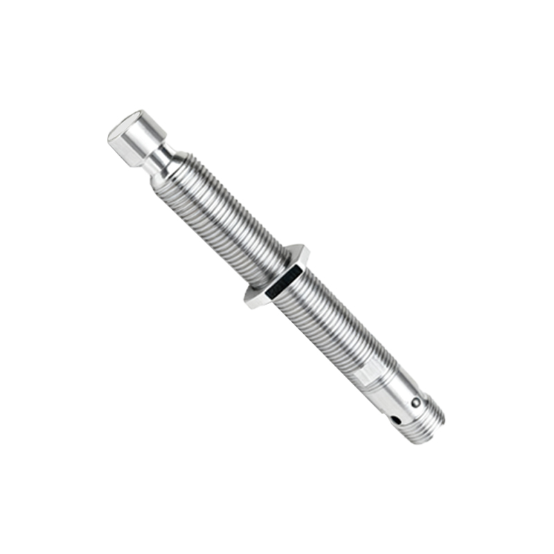
Analog Output: These provide a voltage or current signal (e.g., 0-10V, 4-20mA) proportional to the detection distance.
The "short-circuit" in question almost always pertains to the output signal terminals to simulate an "ON" or detection state, not the power supply terminals (which would cause a catastrophic fault).
Procedure for Short-Circuiting a Digital Output Sensor
The goal here is to bypass the sensor's internal switching mechanism to force the output signal state.
1. Power Down & Lockout/Tagout (LOTO): Isolate and secure all power sources to the sensor and the controlling system (e.g., PLC). This is non-negotiable for safety and equipment protection.
2. Identify Terminals: Locate the sensor's datasheet or wiring diagram. Identify the power supply terminals (typically V+ or Brown wire, and V- or Blue wire) and the output signal terminal (typically Black wire for NPN/PNP, or a designated OUT wire). For a 3-wire sensor, these are V+, V-, and Signal Out.
3. Determine Logic (NPN vs. PNP):
For an NPN (Sinking) Sensor: The output acts as a switch to ground (V-). To simulate an "ON" state, you need to connect the output signal terminal directly to the V- (ground) terminal. This creates the "short-circuit" that closes the switch circuit to ground.
For a PNP (Sourcing) Sensor: The output acts as a switch to the positive supply (V+). To simulate an "ON" state, you need to connect the output signal terminal directly to the V+ terminal.
4. Execution: Using an appropriate insulated jumper wire or a temporary solder bridge, create the connection between the identified terminals as per the logic above. Ensure no stray strands contact other terminals.
5. Re-apply Power & Test: With the short in place, carefully re-apply power to the control system (not necessarily the sensor itself, as its output is being bypassed). The receiving device (PLC input, relay) should now register a permanent "ON" signal, confirming the bypass.
Critical Warnings and Implications
Analog Sensors: Shorting the output of an analog sensor (e.g., tying a 4-20mA output to ground or V+) is highly likely to destroy the sensor's output circuitry. For testing, use a calibrated current/voltage source to simulate the signal instead.
Power Supply Short: NEVER short the V+ and V- terminals of the sensor's power supply. This will cause excessive current flow, potentially damaging the power supply, wiring, and sensor, and creating a fire hazard.
Load Compatibility: Ensure the short-circuit does not exceed the current rating of the receiving PLC input or connected load.
Permanent Damage: Even when done correctly on a digital sensor, this procedure risks damaging the sensor's final output transistor if power is applied to the sensor itself while its output is shorted externally.
Purpose: This technique is valid only for isolating a sensor fault during troubleshooting (e.g., "Is the problem in the sensor or the PLC input card?"). It is not a design feature.
Superior Alternative Methods
Professionals often use safer, non-invasive methods:
PLC Forcing: Most Programmable Logic Controllers allow software forcing of an input to ON/OFF.
Simulation Tools: Dedicated sensor simulators can generate correct PNP/NPN signals.
Test Boxes: Portable test units with pushbuttons can be wired in parallel to