In the realm of industrial automation and machine design, proximity sensors are indispensable components, acting as the silent sentinels that detect the presence or absence of objects without physical contact. For engineers, technicians, and procurement specialists, evaluating and selecting the right sensor often begins with a critical resource: the sample image. This guide delves into the technical significance of proximity sensor sample images, explaining what to look for and how to interpret the visual data they provide.
A high-quality sample image is far more than a marketing graphic; it is a detailed technical snapshot. The primary element is, of course, the sensor itself. A clear, high-resolution image from multiple angles (front, side, rear) allows for precise assessment of the housing material—typically nickel-plated brass, stainless steel (V2A, V4A), or PBT plastic—and its IP (Ingress Protection) rating suitability for the intended environment, be it washdown areas or dusty workshops. The image should clearly show the form factor: cylindrical (e.g., M8, M12, M18, M30 threaded barrels) or rectangular block types. The sensing face must be distinctly visible, indicating whether it is shielded (flush-mountable) or unshielded (non-flush), a crucial factor for installation in metallic surroundings.
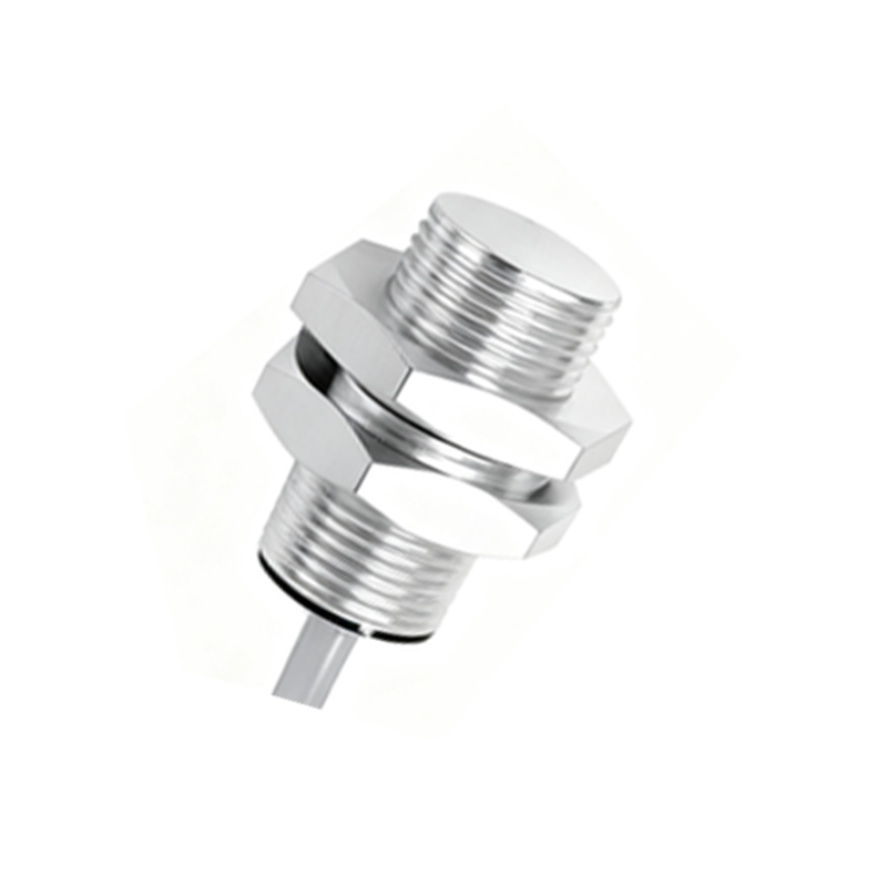
Wiring and connection details are paramount. Sample images should provide a clear view of the connector type, whether it's a standard M12 4-pin or 5-pin quick-disconnect, an M8 connector, or a fixed cable exit with PUR or PVC sheathing. The color-coding of wires according to international standards (Brown for +V, Blue for 0V, Black for output) should be legible. For sensors with LED status indicators, their location and color (typically red or yellow) should be apparent, as this visual feedback is vital for troubleshooting during commissioning and operation.
Contextual application shots are equally valuable. These images demonstrate the sensor in a simulated or real installation. Look for details like the mounting nut, the gap between the sensor face and the target object (the sensing distance), and the target material being detected (e.g., mild steel, aluminum, copper, or plastic). An image showing a sensor detecting a gear tooth or a piston position in a cylinder provides immediate understanding of its practical utility. Some advanced sample sets include diagrams or photos illustrating the detection zones and the hysteresis curve, which is the difference between the switch-on and switch-off points.
When reviewing these images, engineers must cross-reference them with the datasheet specifications. Check the stated sensing range against the apparent scale in the image. Verify the housing length and thread dimensions. The image should corroborate the claimed ruggedness—look for robust construction, laser-etched markings for part number and ratings, and sealed cable entries. For inductive sensors, the image can sometimes indicate the target size factor; a standard target is usually a square of Fe360 steel with a thickness equal to the sensor's diameter.
In conclusion, proximity sensor sample images serve as a critical visual datasheet. They enable rapid preliminary selection, verify physical and installation characteristics, and help avoid costly mismatches. A comprehensive set of images, showcasing build quality, connection options, and application context, reflects a manufacturer's attention to detail and commitment to providing engineers with the necessary tools for informed decision-making. Always insist on clear, technical imagery from suppliers; it is the first practical step toward ensuring reliability and performance in your automated systems.