In the realm of industrial automation and control systems, proximity sensors are indispensable components for non-contact detection. Among various types, reflective proximity sensors, often utilizing an infrared (IR) light source and a phototransistor or photodiode receiver, are widely employed for object detection, counting, and positioning. A clear understanding of their reflective schematic diagram is crucial for engineers for proper selection, integration, and troubleshooting.
The fundamental operating principle of a reflective proximity sensor is based on the emission and reception of light. The core schematic diagram typically illustrates several key components. First is the IR Light Emitting Diode (LED). This component acts as the signal source, emitting a beam of modulated infrared light. Modulation, often at a specific frequency (e.g., several kHz), is critical to distinguish the sensor's own signal from ambient light, thereby enhancing noise immunity and reliability. The driving circuit for the LED, which might include a current-limiting resistor and an oscillator for modulation, is an integral part of the schematic.
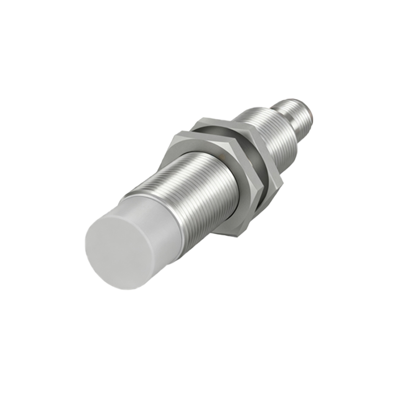
The emitted light travels through the sensor's lens or window and propagates into the detection zone. When no target object is present within the specified sensing range, the light continues to travel away, and the receiver detects minimal reflected signal. The heart of the receiver side is the photodetector, commonly a phototransistor. Its schematic symbol is similar to a standard transistor but with light-sensitive base region. In the absence of sufficient reflected IR light, the phototransistor remains in a high-impedance 'off' state.
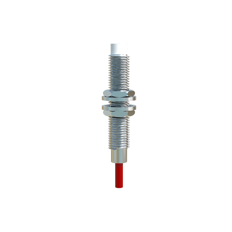
The pivotal moment occurs when a target object enters the sensor's detection field. The surface of the object reflects a portion of the emitted IR light beam back towards the sensor. The reflectivity of the object's material (color, texture, material type) significantly impacts the amount of reflected light and thus the effective sensing distance. The schematic must account for this variable in its sensitivity or threshold settings. The reflected light is focused by the lens onto the sensitive area of the phototransistor.
Upon receiving the modulated IR light, the phototransistor conducts. Its internal resistance drops, allowing current to flow from the collector to the emitter. This change in state is the primary electrical output of the detection event. However, the raw signal from the photodetector is often weak and requires conditioning. This is where the signal processing circuitry, detailed in the schematic, plays a vital role.
A typical schematic will show an amplifier stage following the phototransistor. This operational amplifier (op-amp) circuit boosts the small current change into a more robust voltage signal. Following amplification, a demodulator or filter circuit is employed. Since the emitted light is modulated, the receiver circuit can be tuned to respond only to signals at that specific frequency. This stage effectively filters out DC ambient light and other interfering frequencies, dramatically improving the sensor's stability in varying lighting conditions.
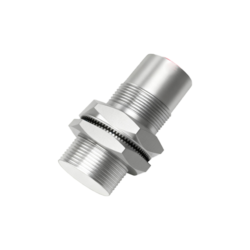
The processed signal then feeds into a comparator circuit. Here, it is compared against a preset reference voltage, which corresponds to the desired sensitivity threshold. The engineer can adjust this threshold, often via a potentiometer shown in the schematic, to set the precise sensing distance or to accommodate different object reflectivities. When the processed signal exceeds the reference voltage, the comparator's output switches state—typically from a high logic level to low, or vice versa, depending on the design (NPN/PNP, NO/NC).
Finally, the output stage is shown. For digital sensors, this is often an open-collector NPN or PNP transistor capable of sinking or sourcing current to drive a load such as a PLC input, relay, or indicator lamp. Protection elements like flyback diodes for inductive loads or series resistors are commonly included in the schematic. For analog output sensors, the schematic would detail a circuit that provides a continuous voltage or current output (e.g., 0-10V, 4-20mA) proportional to the distance or reflectivity of the object.
Analyzing a reflective proximity sensor schematic also involves understanding its limitations. The diagram helps identify potential issues like optical cross-talk between closely mounted sensors, the need for precise alignment, and the effect of highly reflective or absorbent backgrounds. It clarifies why certain materials (transparent, black, or shiny metals) may cause unreliable detection and how internal compensation circuits work to mitigate temperature drift affecting the LED and photodetector.
In conclusion, the reflective schematic diagram of a proximity sensor is more than just a circuit drawing; it is a roadmap of its functionality and performance boundaries. For the industrial engineer, proficiency in interpreting this schematic enables optimal sensor deployment, effective integration into complex control systems, and efficient diagnosis of field issues, ensuring robust and reliable automation processes.