In industrial automation and machinery, proximity sensors are indispensable components for non-contact detection of objects. Their reliability directly impacts system uptime and safety. Therefore, knowing how to effectively test and determine whether a proximity sensor is functioning correctly is a critical skill for maintenance technicians and engineers. This guide outlines practical methods and steps for evaluating sensor health.
First, understand the basic types. Inductive proximity sensors detect metallic objects, capacitive sensors detect both metallic and non-metallic materials, and ultrasonic or photoelectric sensors use sound or light waves. The testing approach varies slightly by type, but core principles remain similar.
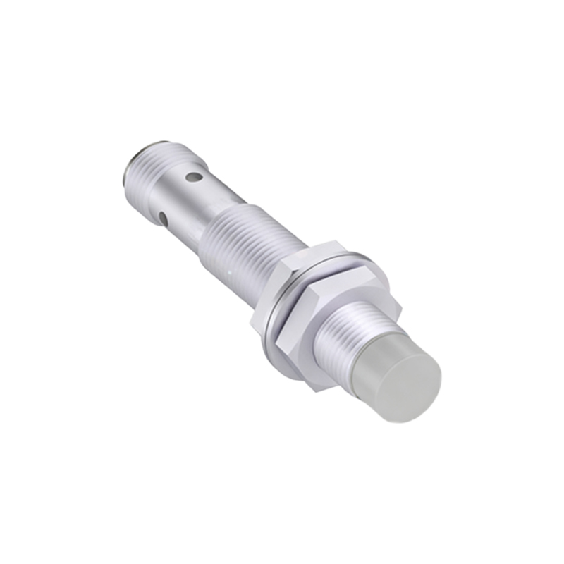
Visual Inspection: Begin with a thorough physical examination. Check the sensor housing for cracks, dents, or signs of impact. Inspect the sensing face for accumulation of dirt, metal shavings, grease, or other contaminants that could attenuate the sensing signal. Verify the integrity of the cable and connector; look for cuts, fraying, or loose pins. A damaged body or cable often leads to intermittent failure or complete malfunction.
Power and Wiring Check: Ensure the sensor is connected to the correct power supply as per its specifications (e.g., 10-30V DC for many DC sensors). Use a multimeter to measure the voltage at the sensor's terminals while connected. Incorrect voltage is a common cause of failure. For 3-wire sensors, confirm the wiring: typically, brown wire to positive (+V), blue wire to negative (0V/Common), and black (or white) wire as the output signal. For 2-wire AC/DC sensors, verify they are wired in series with the load. Loose connections or incorrect wiring will prevent proper operation.
Testing the Sensing Function (Dynamic Test): This is the core functional test.
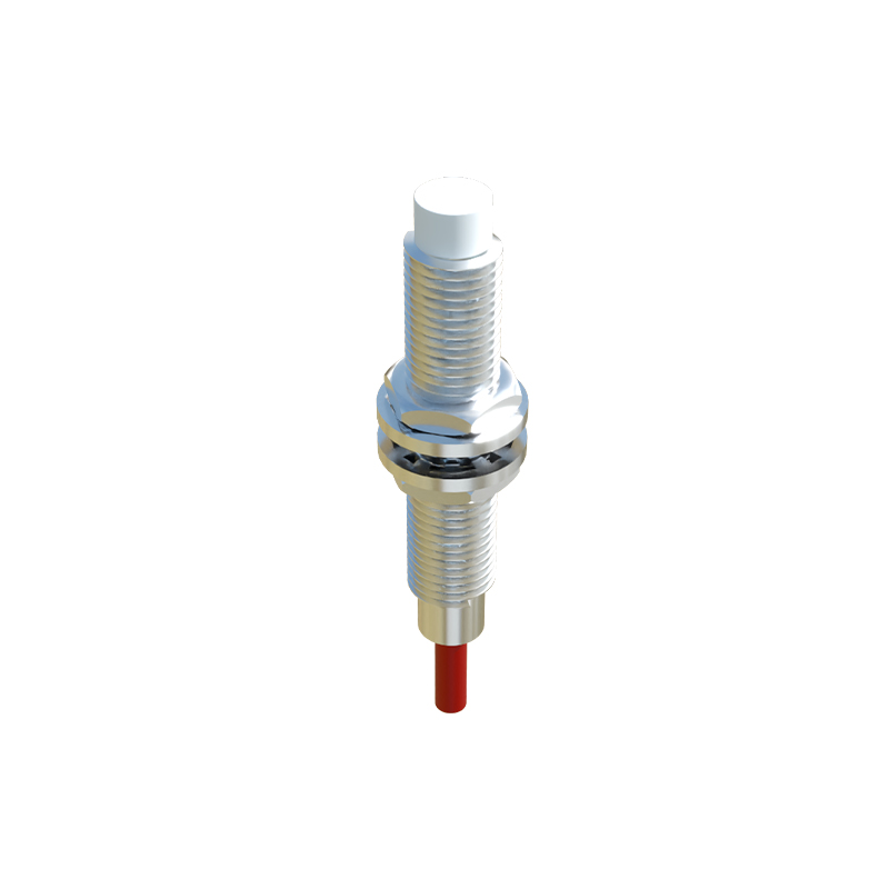
1. Power On: With correct wiring and power applied, the sensor usually has an LED indicator. An unpowered or faulty sensor LED will not light. A steadily lit or flashing LED (depending on model) often indicates power is present and the sensor is in its normal state (no target detected).
2. Trigger the Sensor: Introduce a valid target object into the sensor's specified sensing range. For an inductive sensor, use a standard metal target (like a piece of mild steel). For a capacitive sensor, you can use your hand or the intended material. Move the target directly toward the sensing face.
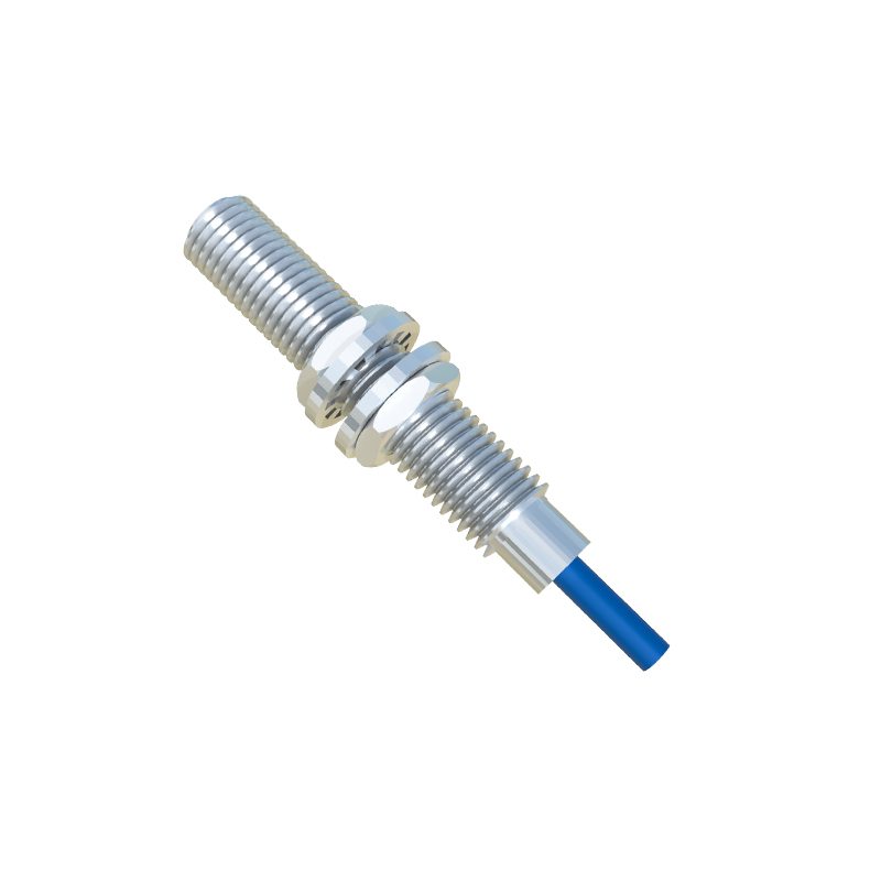
3. Observe the Output: When the target enters the effective range, the sensor's output should switch. The LED indicator typically changes state (e.g., turns off or changes color) to signal activation. Simultaneously, use your multimeter to measure the output signal.
For a PNP (sourcing) sensor, the output voltage (between black wire and blue wire) should switch from near 0V to near the supply voltage (e.g., 24V) when activated.
For an NPN (sinking) sensor, the voltage between the black wire and the brown wire should switch from near supply voltage to near 0V when activated.
For a 2-wire sensor, measure the voltage drop across it; it should significantly decrease when activated, allowing current to flow to the load.
4. Check Sensing Distance: Slowly bring the target closer. Note the point where the output switches on. Compare this "actual sensing distance" to the sensor's rated "nominal sensing distance" (Sn). It should be within 90-110% of Sn under ideal conditions. A significantly reduced sensing distance suggests aging internal components, weak oscillator (in inductive types), or a dirty face.
Additional Diagnostic Steps:
Load Test: Connect the sensor to its intended load (e.g., a PLC input, relay, or indicator lamp) and repeat the trigger test. Sometimes a sensor may test fine with a multimeter's high impedance but fail to drive the actual load due to diminished output current.
Environmental Interference: Check for sources of interference. For inductive sensors, nearby large motors, transformers, or other sensors operating at similar frequencies can cause erratic behavior. Ensure proper shielding and separation. For photoelectric sensors, ambient light or reflective backgrounds may cause false triggers.
Oscilloscope Analysis (Advanced): For persistent, tricky faults, an oscilloscope can reveal the quality of the output signal, showing issues like slow switching times, noise, or a weakened amplitude that a multimeter might miss.
Consult Datasheet: Always refer to the manufacturer's datasheet for specific test procedures, timing diagrams, and performance curves.
Summary of Failure Indicators:
No LED illumination: Check power, wiring, or a completely dead sensor.
LED on but no output change when target is present: Possible