In industrial automation and machinery, proximity sensors are indispensable components for non-contact detection of objects. They play a critical role in positioning, counting, and safety applications. However, a common and disruptive issue is when a proximity sensor fails to detect an object within its specified sensing range. This malfunction can lead to production stoppages, quality defects, or even safety hazards. As an experienced electrical engineer, I will guide you through a systematic, professional approach to diagnosing and resolving this problem.
First and foremost, ensure personal and equipment safety by locking out and tagging out (LOTO) the power source before performing any physical inspection or maintenance.
Step 1: Initial Verification and Observation
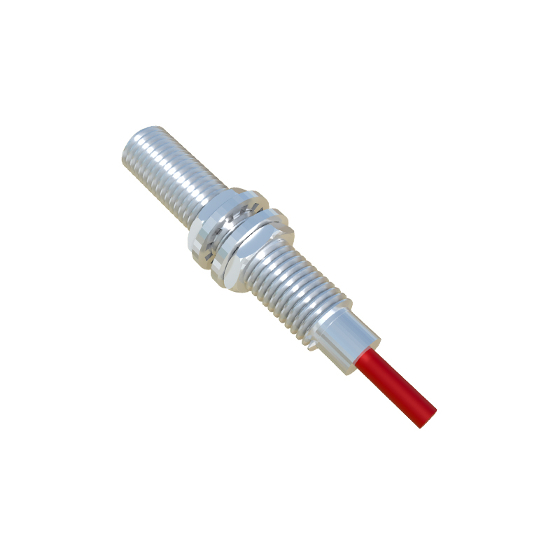
Begin with the basics. Confirm the object you are trying to detect is indeed present and within the sensor's nominal sensing range. Check the sensor's datasheet for its specifications—inductive sensors detect metals, capacitive sensors detect various materials including non-metals, and ultrasonic or photoelectric sensors have different target requirements. Verify the target material, size, and approach speed are compatible. Observe the sensor's indicator LED (if equipped). A solid or blinking light often indicates power and output status, providing the first clue.
Step 2: Power Supply and Wiring Inspection
A significant percentage of sensor failures stem from electrical issues. Using a multimeter, measure the voltage at the sensor's terminals. Ensure it matches the rated supply voltage (e.g., 10-30V DC or 90-250V AC). Check for voltage drops, instability, or excessive noise on the line. Inspect the wiring thoroughly. Look for loose connections, corroded terminals, damaged cables (especially at strain relief points), or short circuits. Verify that the wiring follows the manufacturer's diagram correctly—common errors include mixing up the Brown (positive), Blue (negative), and Black (output) wires on DC 3-wire sensors.
Step 3: Sensor Configuration and Environment
Many modern sensors have configurable parameters. For adjustable sensing distance models, ensure the potentiometer or teach-in procedure hasn't been accidentally altered. For sensors with a hysteresis setting, verify it is appropriate for the application. The operating environment is a frequent culprit. Accumulation of dust, metal chips, oil, or coolant on the sensing face can severely impair performance. Clean the face meticulously with a soft cloth and appropriate cleaner. Also, check for environmental factors like extreme temperatures, strong electromagnetic interference (EMI) from nearby motors or welders, or direct sunlight affecting optical sensors.
Step 4: Mechanical Alignment and Mounting
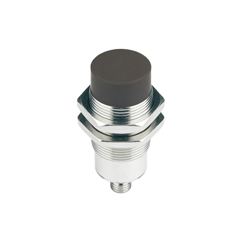
Improper mounting is a common oversight. The sensor must be correctly aligned with the target's path. For inductive and capacitive sensors, the target should approach the center of the sensing face. For cylindrical (barrel) sensors, ensure they are not mounted too flush with a metal bracket, as this can cause shielding and reduce the effective sensing distance. Check for excessive vibration that could loosen the sensor or damage internal components. Verify there is no other metal object or sensor in close proximity causing mutual interference.
Step 5: Load and Output Circuit Check
The sensor might be functioning, but the signal is not reaching the controller. Disconnect the sensor's output wire from the load (e.g., PLC input, relay). Use your multimeter to check the output state when a target is presented. For a PNP (sourcing) sensor, voltage should appear between the output and negative when activated. For an NPN (sinking) sensor, the output should go to near 0V relative to positive. If the output switches correctly, the issue lies downstream—check the PLC input module's health, wiring, and configuration. Also, ensure the load current does not exceed the sensor's maximum switching capacity.
Step 6: Sensor Performance Testing
If all external factors are ruled out, the sensor itself may be faulty. Perform a bench test with a known-good power supply and a standard target (like a piece of mild steel for inductive sensors). Measure the actual sensing distance. If it's significantly less than specified, the oscillator circuit or internal components may be degraded. For photoelectric sensors, check the lens for cracks and ensure the emitter/receiver are clean.
Step 7: Documentation and Replacement
Document all findings, measurements, and actions taken. If the sensor is confirmed defective, replace it with an identical model or a verified equivalent. After replacement, recalibrate if necessary and run a series of functional tests under normal operating conditions to confirm the issue is resolved.
Proactive maintenance, including regular cleaning, electrical checks, and environmental monitoring, can prevent many detection failures. Understanding the sensor's principle of operation is key to efficient troubleshooting. By following this logical sequence—from power and environment to the sensor itself—you can minimize downtime and ensure reliable operation of your automated systems.