In the realm of industrial automation and control systems, 3-wire proximity sensors are ubiquitous components, prized for their reliability in non-contact detection of metallic objects. A fundamental aspect of their installation and operation lies in correctly interpreting and connecting their typically color-coded leads: brown, black, and blue. This wiring standard, though common, is crucial for ensuring proper sensor functionality, system safety, and optimal performance.
The color coding for DC-powered 3-wire proximity sensors generally follows a near-universal convention. The brown wire is designated as the positive supply line. This conductor must be connected to the positive terminal of the DC power source. It provides the operating voltage necessary for the sensor's internal circuitry. The blue wire is universally recognized as the negative or common return line. It must be connected to the negative terminal or ground of the DC power supply, completing the circuit for the sensor's power requirements.
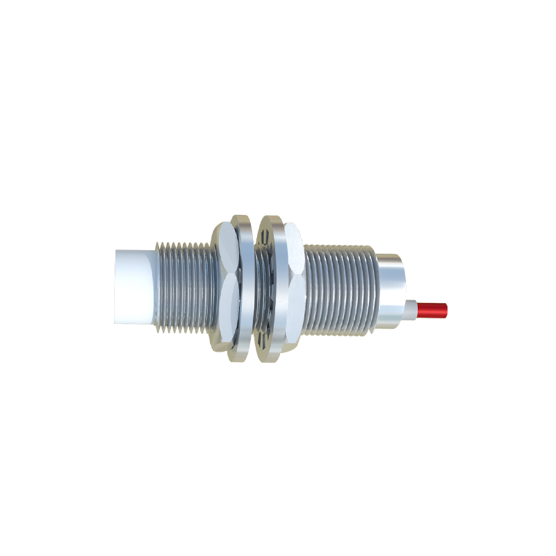
The critical functionality of the sensor is carried by the black wire. This is the output signal line. The behavior of this output depends on the sensor's type. In a normally open (NO) configuration, the black wire acts as a switching output. When no target is within the sensor's detection range, the circuit between the black wire and the blue wire (for an NPN sensor) or the brown wire (for a PNP sensor) is open, meaning no output current flows. When a target is detected, this switch closes, allowing current to flow through the output to the load. Conversely, a normally closed (NC) sensor has the opposite logic: the output circuit is closed when idle and opens upon detection.
Understanding the distinction between PNP (sourcing) and NPN (sinking) output types is paramount and is directly related to how the black wire is utilized. A sensor with a PNP output essentially switches the positive voltage. In this setup, the load (e.g., a PLC input, relay coil) is connected between the black wire (the switched positive) and the blue wire (common negative). When activated, the PNP sensor sources current from the brown wire through the black wire to the load. A sensor with an NPN output switches the negative or ground path. Here, the load is connected between the brown wire (positive supply) and the black wire. When activated, the NPN sensor sinks current from the load, through the black wire, to the blue wire (common negative). Misidentifying this can lead to incorrect PLC input responses or potential damage.
The consistent use of brown, black, and blue across manufacturers greatly simplifies maintenance and troubleshooting. An electrician or technician encountering a faulty sensor can often trace issues directly to these connections. Common problems include reversed brown and blue connections (preventing the sensor from powering on), incorrect interpretation of the black wire's output type relative to the controller's input requirements (resulting in no signal change), or loose terminations. A systematic check always starts with verifying DC power (typically 10-30V DC) between brown (+) and blue (-), followed by monitoring the black wire's voltage state in relation to detection events.
When integrating these sensors into a control panel, adherence to electrical codes and best practices is non-negotiable. This includes using proper gauge wire, secure terminal blocks or connectors, and implementing appropriate fusing or circuit protection on the supply line. For sensors in high-vibration environments, crimped ferrules on the wire ends are recommended to prevent strand breakage. Furthermore, while the color code is standard, the ultimate authority is always the sensor's datasheet or nameplate, which may specify exceptions or provide wiring diagrams for specific models.
In summary, the brown, black, and blue wires of a 3-wire proximity sensor form a simple yet elegant interface between detection logic and control systems. The brown wire energizes, the blue wire completes the circuit, and the black wire communicates the detection event. Mastery of their roles—especially the critical difference between PNP (sourcing via black) and NPN (sinking via black) configurations—is essential for any professional designing, installing, or maintaining modern automated equipment. This knowledge ensures not only operational success but also contributes to the overall safety and efficiency of industrial processes.