Proximity sensors are widely used in industrial automation for detecting the presence or absence of objects without physical contact. These devices operate based on various principles, with inductive, capacitive, and photoelectric types being the most common. Understanding their working mechanisms and proper wiring is essential for reliable system integration.
Inductive proximity sensors detect metallic objects. They contain an oscillator circuit that generates a high-frequency electromagnetic field at the sensing face. When a metal target enters this field, eddy currents are induced in the target, causing a change in the oscillator's amplitude. This change is detected by a threshold circuit, which triggers the sensor's output switch. Inductive sensors are ideal for harsh environments and can detect ferrous and non-ferrous metals, though sensing ranges vary with material type.
Capacitive proximity sensors can detect both metallic and non-metallic materials, including liquids, plastics, and wood. They utilize a capacitor formed by the sensor's electrode and the ground. As an object approaches, the dielectric constant changes, altering the capacitance and triggering oscillation. The sensor's circuit monitors this shift to activate the output. These sensors are suitable for level detection or material handling applications.
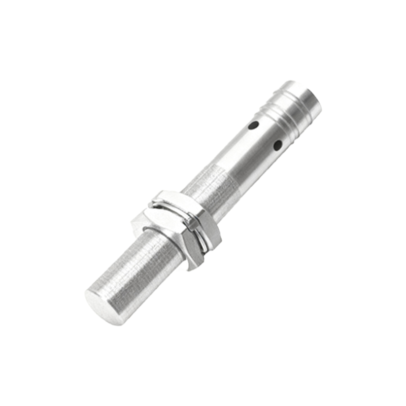
Photoelectric sensors use light beams to detect objects. An emitter sends light (often infrared) to a receiver. When an object interrupts or reflects the beam, the receiver detects the change and switches the output. Types include through-beam, retro-reflective, and diffuse reflective models, each suited for different sensing distances and environmental conditions.
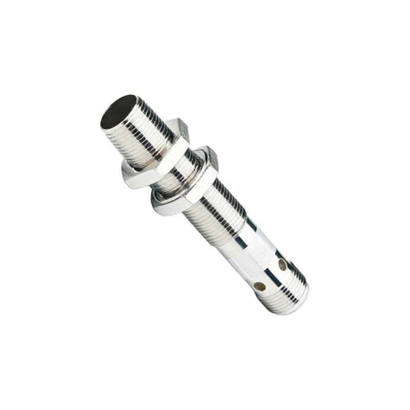
Wiring proximity sensors correctly is crucial for safety and functionality. Most sensors have three wires: brown (positive), blue (negative), and black (output). For DC sensors, connect brown to the positive supply voltage (typically 10-30 VDC) and blue to the negative or ground. The black wire is the output, which switches the load (e.g., a PLC input or relay). Ensure the load is within the sensor's current rating. For AC sensors, wiring may involve two or four wires, with attention to live and neutral connections.

Always refer to the manufacturer's datasheet for specific wiring diagrams and specifications. Proper installation includes avoiding metal surfaces that could interfere with sensing, using shielded cables in electrically noisy environments, and ensuring correct polarity for DC models. Regular maintenance, such as cleaning the sensing face, helps prevent false triggers and extends sensor life.
In summary, proximity sensors offer non-contact detection with high reliability. Selecting the right type based on application needs—inductive for metals, capacitive for diverse materials, or photoelectric for long-range—ensures optimal performance. Correct wiring and installation practices further enhance system efficiency and safety in industrial setups.