In industrial automation, integrating sensing devices with programmable logic controllers (PLCs) is a fundamental task. Two-wire proximity sensors are widely used due to their simplicity and cost-effectiveness. Unlike three-wire sensors that require separate power and signal lines, two-wire sensors combine both functions into a single loop, making wiring more straightforward but requiring careful consideration of electrical characteristics. This article provides a step-by-step guide on how to properly connect a two-wire proximity sensor to a PLC, ensuring reliable operation in various applications.
First, it is essential to understand the basic operating principle of a two-wire proximity sensor. These sensors are typically designed to work with direct current (DC) power supplies, commonly 10-30 VDC. They function as a switch that closes or opens based on the presence or absence of a target object. When the sensor detects an object, it allows current to flow through the circuit, effectively acting as a closed switch. In the absence of a target, the circuit remains open, and minimal leakage current may be present. The key advantage is that they can be connected in series with the PLC input, similar to a mechanical limit switch, without needing an external power source at the sensor end.
Before starting the connection process, gather the necessary components: a two-wire DC proximity sensor (ensuring it matches the PLC's input specifications), a DC power supply compatible with both the sensor and PLC, appropriate cables, and tools for wiring. Always refer to the datasheets of the sensor and PLC for voltage, current, and polarity requirements to prevent damage. Safety is paramount—disconnect all power sources before beginning installation to avoid electrical hazards.
The connection procedure involves several critical steps. Begin by identifying the terminals on the two-wire sensor. Typically, one wire is for positive voltage (often brown) and the other is for the output signal (often blue or black). However, colors can vary by manufacturer, so verify using the sensor's documentation. Next, examine the PLC digital input module. Most PLC inputs are sinking or sourcing types, which determines how the sensor should be wired. For a sinking input (common on many PLCs), the input point receives current from the sensor. In this setup, connect the positive terminal of the DC power supply to the positive wire of the sensor. Then, connect the sensor's output wire to the PLC's input terminal. Finally, link the common terminal of the PLC input module to the negative side of the power supply. This completes the circuit, allowing the sensor to control the PLC input state.
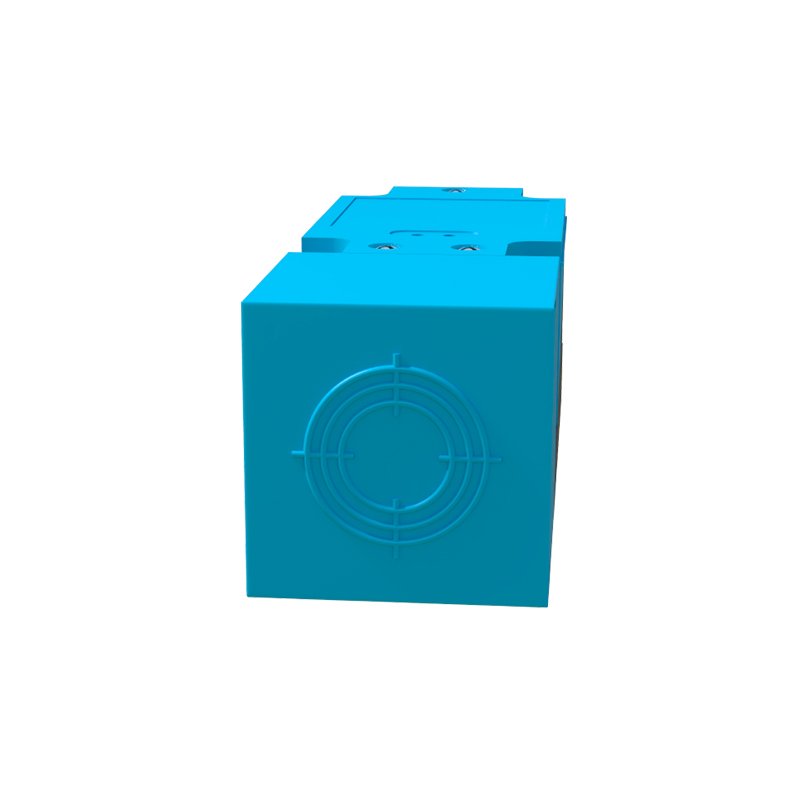
If using a sourcing PLC input, where the input provides current to the sensor, the wiring differs slightly. Connect the positive terminal of the power supply to the PLC input common. Then, wire the PLC input point to the positive wire of the sensor. The sensor's output wire should be connected to the negative side of the power supply. Ensure all connections are secure and insulated to prevent short circuits. After wiring, apply power and test the sensor by introducing a target object. The PLC input indicator should activate accordingly, confirming successful integration.
Several practical considerations can impact performance. Two-wire sensors have a residual current (leakage current) even when in the off state, which might be sufficient to keep a PLC input active unintentionally. To avoid this, check that the leakage current is below the PLC input's minimum off-state current threshold. If necessary, use a bleeder resistor in parallel with the PLC input to dissipate excess current. Additionally, voltage drop across the sensor can be significant over long cable runs, potentially causing the PLC input to not register correctly. Calculate the total loop resistance, including cable resistance, to ensure the voltage at the PLC input remains within its operational range. Shielding cables may also be required in electrically noisy environments to prevent false triggering.
Troubleshooting common issues involves verifying power supply voltage, checking for loose connections, and confirming sensor alignment with targets. If the PLC input does not respond, use a multimeter to measure voltage at the input terminals while activating the sensor. The reading should shift distinctly between on and off states. Also, ensure the sensor's sensing distance and target material are compatible, as factors like metal type can affect detection. Regular maintenance, such as cleaning the sensor face and inspecting cables for wear, helps sustain long-term reliability.
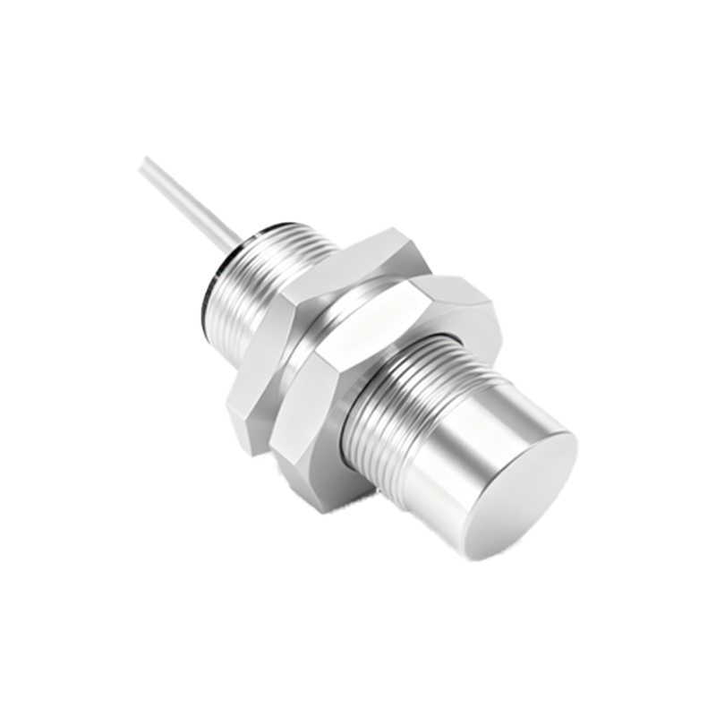
In summary, connecting a two-wire proximity sensor to a PLC is a straightforward process when following proper guidelines. By understanding the sensor's operation, adhering to correct wiring methods based on PLC input type, and accounting for electrical characteristics like leakage current and voltage drop, engineers can achieve robust and efficient automation systems. This integration is crucial in applications ranging from conveyor systems to packaging machinery, where precise object detection directly influences productivity and safety. Always prioritize manufacturer instructions and industry standards to ensure optimal performance and compliance.